10-31
Cisco ONS 15454 DWDM Reference Manual, R8.5
78-18343-02
Chapter 10 Network Reference
10.8.2 System Level Gain Tilt Control
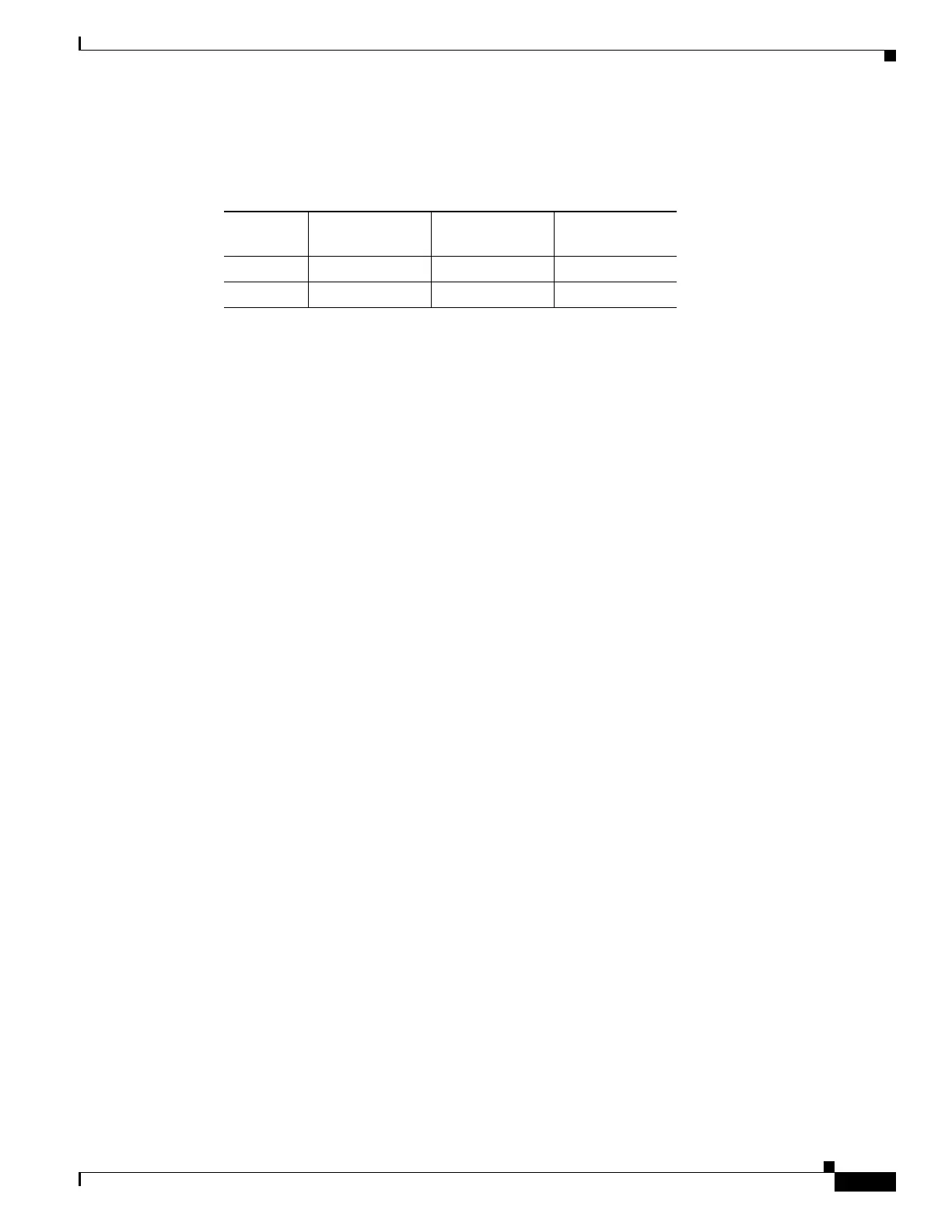
Table 10-2 shows the flat output gain range limits for the OPT-BST and OPT-PRE cards, as well as the
maximum (worst case) values of gain tilt and gain ripple expected in the specific gain range.
If the operating gain value is outside of the range shown in Table 10-2, the EDFA introduces a tilt
contribution for which the card itself cannot directly compensate. This condition is managed in different
ways, depending the amplifier card type:
• OPT-BST—The OPT-BST amplifier is, by design, not allowed to work outside the zero tilt range.
Cisco TransportPlanner network designs use the OPT-BST amplifier card only when the gain is less
than or equal to 20 dB.
• OPT-PRE—Cisco TransportPlanner allows network designs even if the operating gain value is equal
to or greater than 21 dB. In this case, a system-level tilt compensation strategy is adopted by the
DWDM system. A more detailed explanation is given in 10.8.2 System Level Gain Tilt Control,
page 10-31.
10.8.2 System Level Gain Tilt Control
System level gain tilt control for OPT-PRE cards is achievable with two main scenarios:
• Without an ROADM node
• With an ROADM node
10.8.2.1 System Gain Tilt Compensation Without ROADM Nodes
When an OPT-PRE card along a specific line direction (Side A-to-Side B or Side B-to-Side A) is
working outside the flat output gain range (G > 21 dB), the unregulated tilt is compensated for in spans
that are not connected to ROADM nodes by configuring an equal but opposite tilt on one or more of the
amplifiers in the downstream direction. The number of downstream amplifiers involved depends on the
amount of tilt compensation needed and the gain setpoint of the amplifiers that are involved. See
Figure 10-22.
Table 10-2 Flat Output Gain Range Limits
Amplifier
Card Type
Flat Output
Gain Range
Gain Tilt
(Maximum)
Gain Ripple
(Maximum)
OPT-BST G < 20 dB 0.5 dB 1.5 dB
OPT-PRE G < 21 dB 0.5 dB 1.5 dB

 Loading...


