6-26
Cisco ONS 15454 DWDM Reference Manual, R8.5
78-18343-02
Chapter 6 Optical Add/Drop Cards
6.7.2 AD-4B-xx.x Card-Level Indicators
For information on the associated TL1 AIDs for the optical power monitoring points, refer the “CTC
Port Numbers and TL1 Aids” section in Cisco ONS SONET TL1 Command Guide, Release 8.5.
6.7.2 AD-4B-xx.x Card-Level Indicators
The AD-4B-xx.x card has three card-level LED indicators, described in Table 6-18.
6.7.3 AD-4B-xx.x Port-Level Indicators
You can find the status of the card port using the LCD screen on the ONS 15454 fan-tray assembly. Use
the LCD to view the status of any port or card slot; the screen displays the number and severity of alarms
for a given port or slot. The AD-4B-xx.x has 12 LC-PC-II optical ports: eight for add/drop band client
input and output, two for express channel input and output, and two for communication.
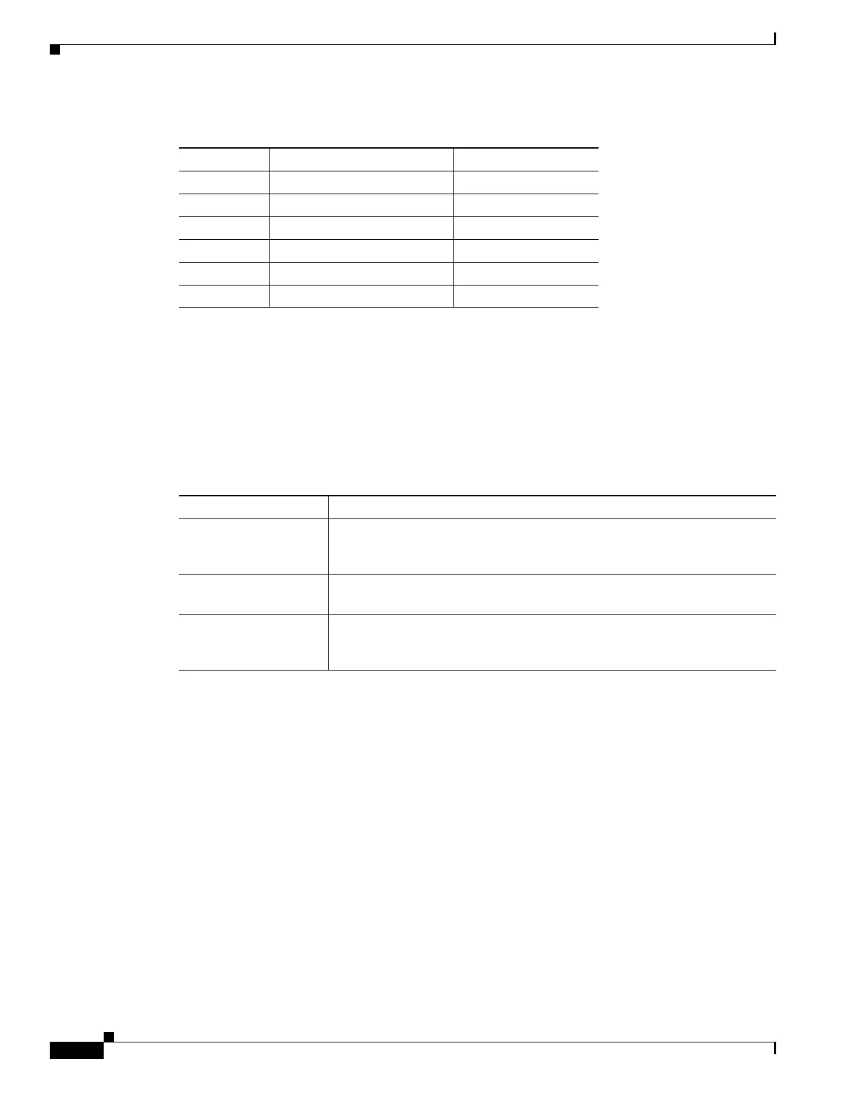
Table 6-17 AD-4B-xx.x Port Calibration
Photodiode CTC Type Name Calibrated to Port
P1–P4 ADD COM TX
P5–P8 DROP DROP TX
P9 IN EXP EXP RX
P10 OUT EXP EXP TX
P11 IN COM COM RX
V1 OUT COM COM TX
Table 6-18 AD-4B-xx.x Card-Level Indicators
Card-Level Indicators Description
Red FAIL LED The red FAIL LED indicates that the card’s processor is not ready or that
there is an internal hardware failure. Replace the card if the red FAIL LED
persists.
Green ACT LED The green ACT LED indicates that the AD-4B-xx.x card is carrying traffic
or is traffic-ready.
Amber SF LED The amber SF LED indicates a signal failure. The amber SF LED also
illuminates when the transmit and receive fibers are incorrectly connected.
When the fibers are properly connected, the light turns off.

 Loading...


