9-27
Cisco ONS 15454 DWDM Reference Manual, R8.5
78-18343-02
Chapter 9 Node Reference
9.3.3 Optical Side Configurations
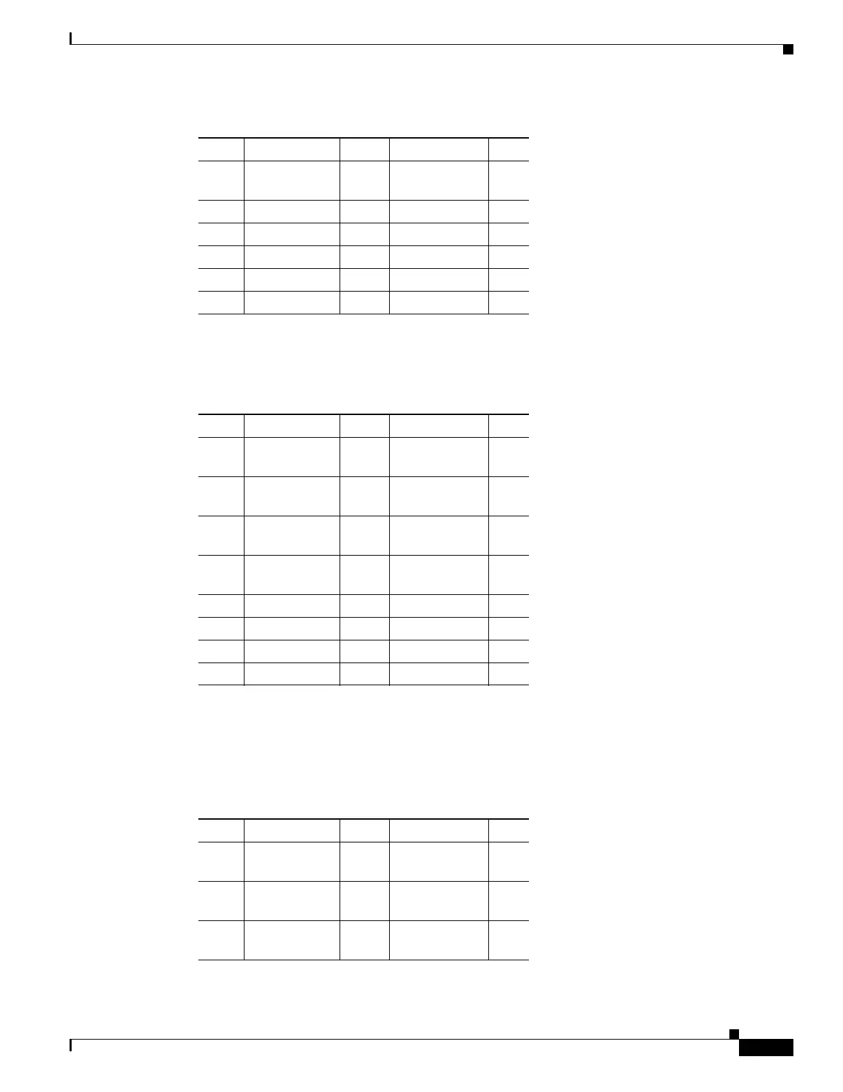
Table 9-5 shows a protected four-degree mesh node example. In the example, Sides A through D are
assigned to Slots 1 through 6 in Shelves 1 through 4.
Table 9-6 shows a protected four-degree mesh node example. In the example, Sides A through D are
assigned to Slots 1 through 4 in Shelves 1 through 4, and TXP, MXP, ADM-10G, GE_XP, 10GE_XP,
GE_XPE, or 10GE_XPE cards are installed in Shelves 1 through 4, Slots 12-17, and Shelves 5 through
8, Slots 1 through 6 and 12 through 17.
3WXC Line
Termination
D TXP/MXP —
4 TXP/MXP n/a TXP/MXP —
5 TXP/MXP n/a TXP/MXP —
6 TXP/MXP n/a TXP/MXP —
7 TXP/MXP n/a TXP/MXP —
8 TXP/MXP n/a TXP/MXP —
Table 9-4 Multishelf Four-Degree Mesh Node Layout Example (continued)
Shelf Slots 1–6 Side Slots 12–17 Side
Table 9-5 Multishelf Four-Degree Protected Mesh Node Layout Example
Shelf Slots 1–6 Side Slots 12–17 Side
1WXC Line
Termination
A TXP/MXP —
2WXC Line
Termination
B TXP/MXP —
3WXC Line
Termination
C TXP/MXP —
4WXC Line
Termination
D TXP/MXP —
5 TXP/MXP — TXP/MXP —
6 TXP/MXP — TXP/MXP —
7 TXP/MXP — TXP/MXP —
8 TXP/MXP — TXP/MXP —
Table 9-6 Multishelf Four-Degree Protected Mesh Node Layout Example
Shelf Slots 1–6 Side Slots 12–17 Side
1WXC Line
Termination
A TXP/MXP —
2WXC Line
Termination
B TXP/MXP —
3WXC Line
Termination
C TXP/MXP —

 Loading...


