7-29
Cisco ONS 15454 DWDM Reference Manual, R8.5
78-18343-02
Chapter 7 Reconfigurable Optical Add/Drop Cards
7.5.6 32DMX Card-Level Indicators
7.5.6 32DMX Card-Level Indicators
Table 7-16 describes the three card-level LED indicators on the 32DMX card.
7.5.7 32DMX Port-Level Indicators
You can find the alarm status of the 32DMX card’s ports using the LCD screen on the ONS 15454
fan-tray assembly. The screen displays the number and severity of alarms on a given port or slot. For the
procedure to view these counts, refer to “Manage Alarms” in the Cisco ONS 15454 DWDM Procedure
Guide.
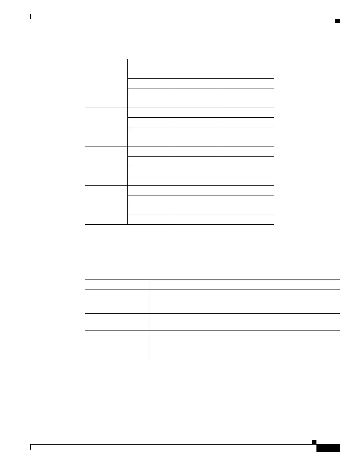
B46.1 46.1 193.9 1546.12
46.9 193.8 1546.92
47.7 193.7 1547.72
48.5 193.6 1548.51
B50.1 50.1 193.4 1550.12
50.9 193.3 1550.92
51.7 193.2 1551.72
52.5 193.1 1552.52
B54.1 54.1 192.9 1554.13
54.9 192.8 1554.94
55.7 192.7 1555.75
56.5 192.6 1556.55
B58.1 58.1 192.4 1558.17
58.9 192.3 1558.98
59.7 192.2 1559.79
60.6 192.1 1560.61
Table 7-15 32DMX Channel Allocation Plan (continued)
Band ID Channel Label Frequency (THz) Wavelength (nm)
Table 7-16 32DMX Card-Level Indicators
Card-Level Indicators Description
Red FAIL LED The red FAIL LED indicates that the card’s processor is not ready or that an
internal hardware failure occurred. Replace the card if the red FAIL LED
persists.
Green ACT LED The green ACT LED indicates that the 32DMX card is carrying traffic or is
traffic-ready.
Amber SF LED The amber SF LED indicates a signal failure on one or more of the card’s
ports. The amber SF LED also turns on when the transmit and receive fibers
are incorrectly connected. When the fibers are properly connected, the light
turns off.

 Loading...


