1-31
Cisco ONS 15454 DWDM Reference Manual, R8.5
78-18343-02
Chapter 1 Shelf Assembly Hardware
1.7.3 Alarm Interface Panel
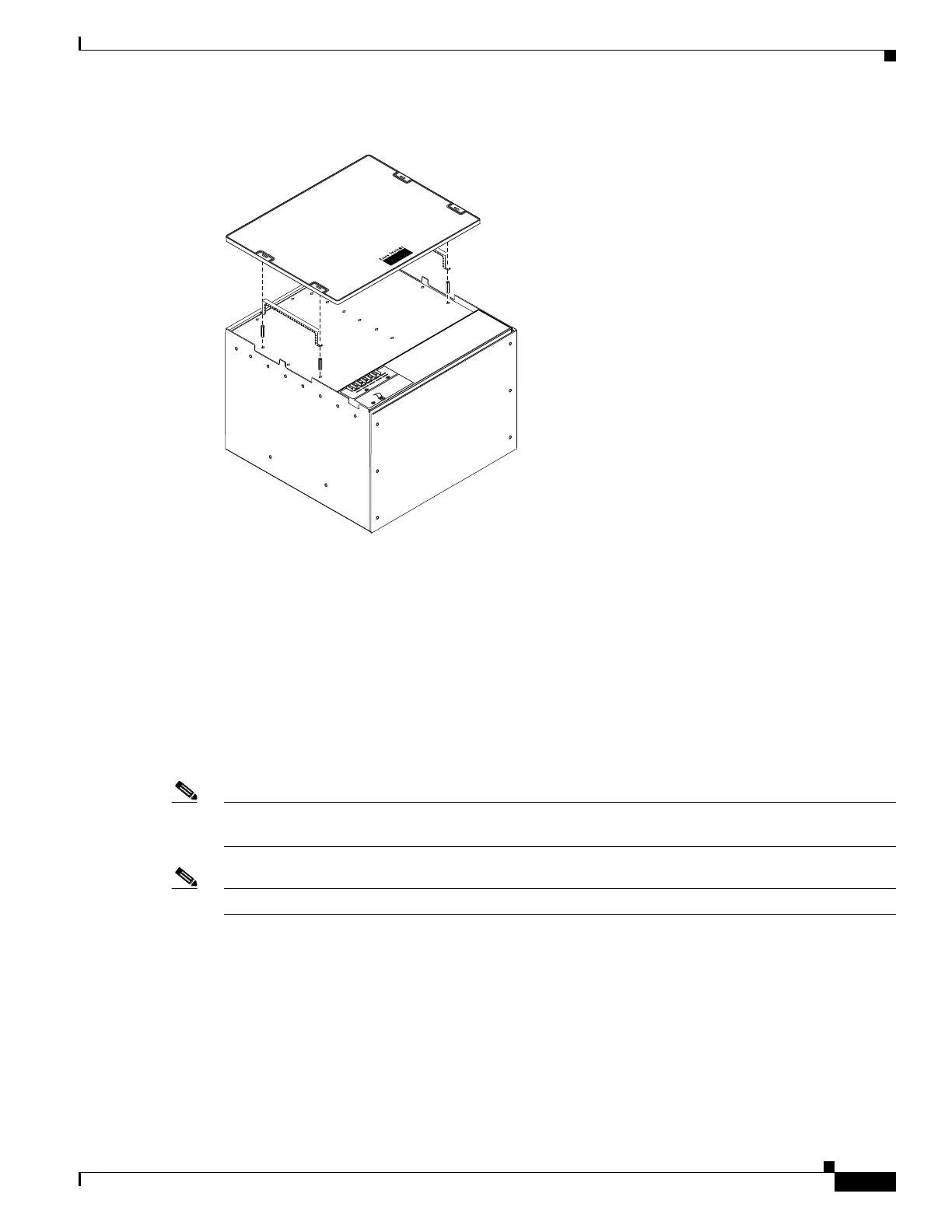
Figure 1-30 Installing the Plastic Rear Cover with Spacers
1.7.3 Alarm Interface Panel
The AIP is located above the alarm contacts on the lower section of the backplane. The AIP provides
surge protection for the ONS 15454 ANSI. It also provides an interface from the backplane to the
fan-tray assembly and LCD. The AIP plugs into the backplane using a 96-pin DIN connector and is held
in place with two retaining screws. The panel has a nonvolatile memory chip that stores the unique node
address (MAC address). The MAC address identifies the nodes that support circuits. It allows
Cisco Transport Controller (CTC) to determine circuit sources, destinations, and spans. The
TCC2/TCC2P cards in the ONS 15454 ANSI also use the MAC address to store the node database.
Note The 5-A AIP (73-7665-XX) is required when installing fan-tray assembly 15454-FTA3 or
15454-CC-FTA, which comes preinstalled on the shelf assembly (15454-SA-ANSI or 15454-SA-HD).
Note A blown fuse on the AIP board can cause the LCD display to go blank.
1.7.4 Alarm Interface Panel Replacement
If the AIP fails, a MAC Fail alarm appears on the CTC Alarms menu and/or the LCD display on the
fan-tray assembly goes blank. To perform an in-service replacement of the AIP, you must contact the
Cisco Technical Assistance Center (Cisco TAC). For contact information, see the “Obtaining
Documentation and Submitting a Service Request” section on page lxiv.
55374
R
E
T
1
C
A
U
T
I
O
N
:
R
e
m
o
v
e
p
o
w
e
r
f
r
o
m
b
o
th
th
e
B
A
T
1
a
n
d
te
r
m
in
a
l
b
l
o
c
k
s
p
r
io
r
t
o
s
e
r
v
ic
in
g
S
U
IT
A
B
L
E
F
O
R
M
O
U
N
T
IN
G
O
N
A
N
O
N
-
C
O
M
B
U
S
T
IB
L
E
S
U
R
F
A
C
E
.
P
L
E
A
S
E
R
E
F
E
R
T
O
I
N
S
T
A
L
L
A
T
I
O
N
IN
S
T
R
U
C
T
IO
N
S
.
-
4
2
T
O
-
5
7
V
d
c
6
5
0
W
a
tt
s
M
a
x
im
u
m
B
A
T
1
R
E
T
2
B
A
T
2

 Loading...


