2-5
Cisco ONS 15454 DWDM Reference Manual, R8.5
78-18343-02
Chapter 2 Common Control Cards
2.2.4 Network-Level Indicators
2.2.4 Network-Level Indicators
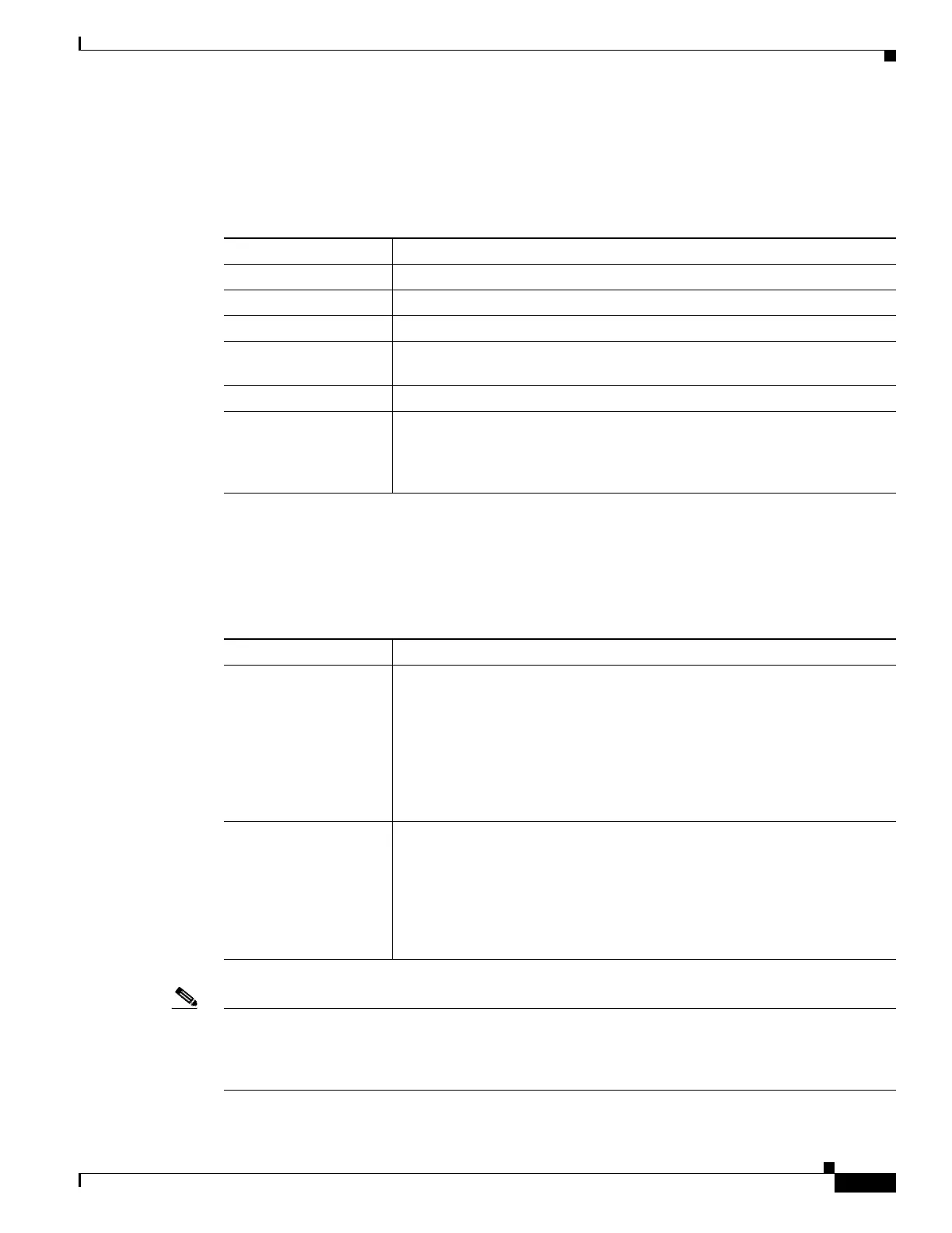
Table 2-2 describes the six network-level LEDs on the TCC2 faceplate.
2.2.5 Power-Level Indicators
Table 2-3 describes the two power-level LEDs on the TCC2 faceplate.
Note For ONS 15454 ETSI shelf, the power-level LEDs are either green or red. The LED is green when the
voltage on supply inputs is between the extremely low battery voltage and extremely high battery voltage
thresholds. The LED is red when the voltage on supply inputs is above extremely high battery voltage
or below extremely low battery voltage thresholds.
Table 2-2 TCC2 Network-Level Indicators
System-Level LEDs Definition
Red CRIT LED Indicates critical alarms in the network at the local terminal.
Red MAJ LED Indicates major alarms in the network at the local terminal.
Yellow MIN LED Indicates minor alarms in the network at the local terminal.
Red REM LED Provides first-level alarm isolation. The remote (REM) LED turns red when
an alarm is present in one or more of the remote terminals.
Green SYNC LED Indicates that node timing is synchronized to an external reference.
Green ACO LED After pressing the alarm cutoff (ACO) button, the ACO LED turns green.
The ACO button opens the audible alarm closure on the backplane. ACO is
stopped if a new alarm occurs. After the originating alarm is cleared, the
ACO LED and audible alarm control are reset.
Table 2-3 TCC2 Power-Level Indicators
Power-Level LEDs Definition
Green/Amber/Red
PWR A LED
The PWR A LED is green when the voltage on supply input A is between the
low battery voltage (LWBATVG) and high battery voltage (HIBATVG)
thresholds. The LED is amber when the voltage on supply input A is between
the high battery voltage and extremely high battery voltage (EHIBATVG)
thresholds or between the low battery voltage and extremely low battery
voltage (ELWBATVG) thresholds. The LED is red when the voltage on
supply input A is above extremely high battery voltage or below extremely
low battery voltage thresholds.
Green/Amber/Red
PWR B LED
The PWR B LED is green when the voltage on supply input B is between the
low battery voltage and high battery voltage thresholds. The LED is amber
when the voltage on supply input B is between the high battery voltage and
extremely high battery voltage thresholds or between the low battery voltage
and extremely low battery voltage thresholds. The LED is red when the
voltage on supply input B is above extremely high battery voltage or below
extremely low battery voltage thresholds.

 Loading...


