7-71
Cisco ONS 15454 DWDM Reference Manual, R8.5
78-18343-02
Chapter 7 Reconfigurable Optical Add/Drop Cards
7.13.3 MMU Power Monitoring
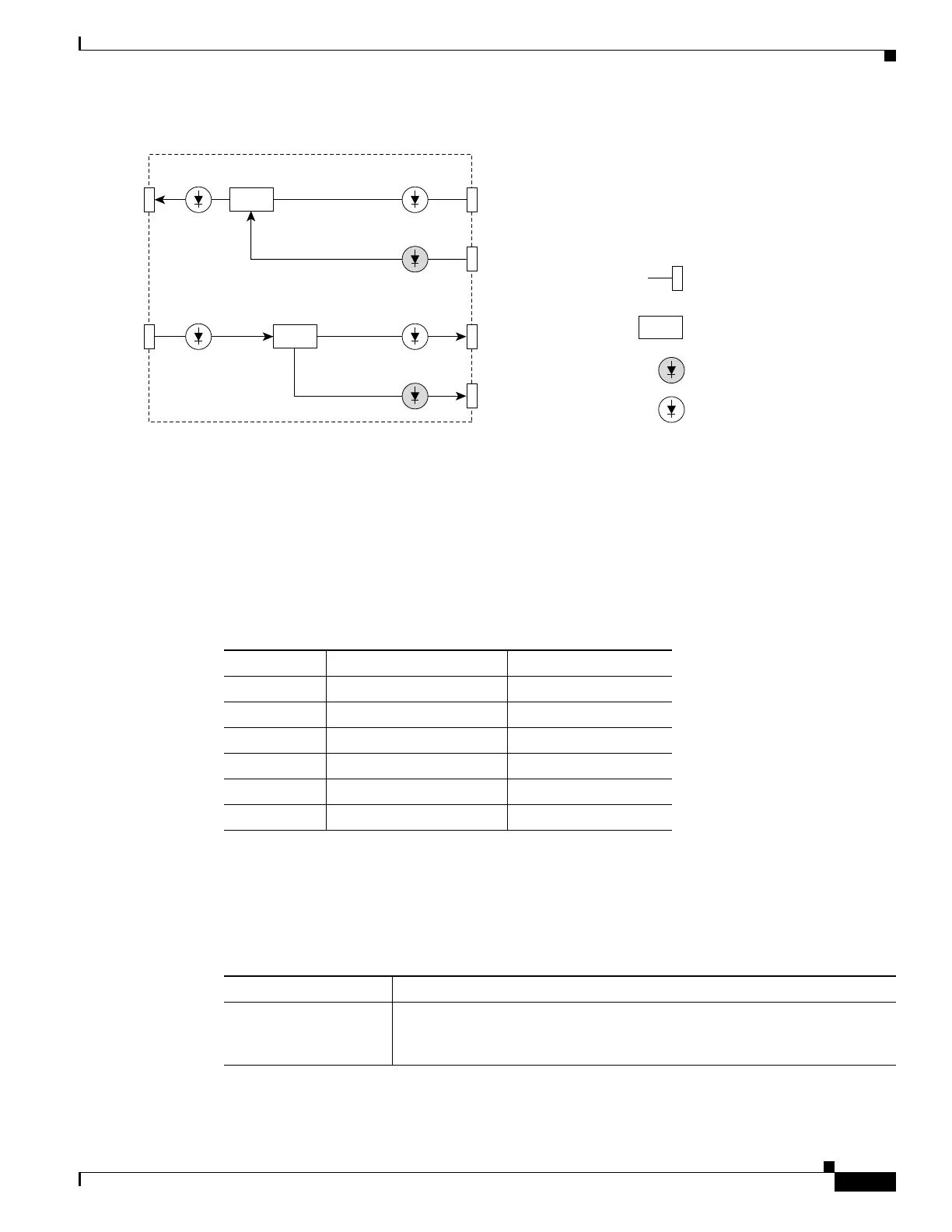
Figure 7-36 MMU Block Diagram
7.13.3 MMU Power Monitoring
Physical photodiodes P1 through P3 monitor the power for the MMU card. The returned power level
values are calibrated to the ports as shown in Table 7-41. VP1 to VP3 are virtual photodiodes that have
been created by adding (by software computation) the relevant path insertion losses of the optical
splitters (stored in the module) to the real photodiode (P1 to P3) measurement.
7.13.4 MMU Card-Level Indicators
Table 7-42 describes the three card-level LED indicators on the MMU card.
145191
COM TX
VPD2 75/25
PD1
EXP RX
PD2
EXP A RX
COM RX
VPD3 95/5
95/5
VPD1
EXP TX
Legend
LC PC II Connector
Optical splitter/coupler
Real photodiode
Virtual photodiode
PD3
EXP A TX
Table 7-41 MMU Port Calibration
Photodiode CTC Type Name Calibrated to Port
P1 1 (EXP-RX) EXP RX
P2 5 (EXP A-RX) EXP A RX
P3 6 (EXP A-TX) EXP A TX
VP1 2 (EXP-TX) EXP TX
VP2 4 (COM-TX) COM TX
VP3 3 (COM-RX) COM RX
Table 7-42 MMU Card-Level Indicators
Card-Level Indicators Description
Red FAIL LED The red FAIL LED indicates that the card’s processor is not ready or that n
internal hardware failure occurred. Replace the card if the red FAIL LED
persists.

 Loading...


