1-57
Cisco ONS 15454 DWDM Reference Manual, R8.5
78-18343-02
Chapter 1 Shelf Assembly Hardware
1.15.1 Alarm Contact Connections
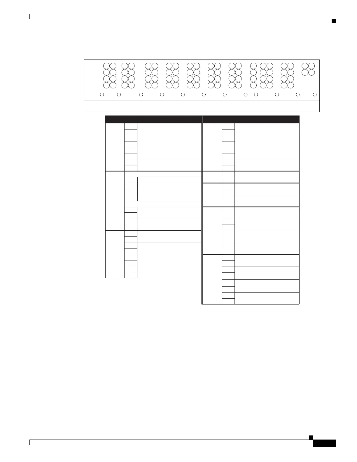
Figure 1-54 ONS 15454 ANSI Backplane Pinouts
1.15.1 Alarm Contact Connections
The alarm pin field supports up to 17 alarm contacts, including four audible alarms, four visual alarms,
one alarm cutoff (ACO), and four user-definable alarm input and output contacts.
Audible alarm contacts are in the LOCAL ALARM AUD pin field and visual contacts are in the LOCAL
ALARM VIS pin field. Both of these alarms are in the LOCAL ALARMS category. User-definable
contacts are in the ENVIR ALARM IN (external alarm) and ENVIR ALARM OUT (external control)
pin fields. These alarms are in the ENVIR ALARMS category; you must have the AIC-I card installed
to use the ENVIR ALARMS. Alarm contacts are Normally Open (N/O), meaning that the system closes
the alarm contacts when the corresponding alarm conditions are present. Each alarm contact consists of
Field Pin Function Field Pin Function
BITS A1 BITS Output 2 negative (-)
ENVIR
ALARMS
OUT
N/O
A1 Normally open output pair number 1
B1 BITS Output 2 positive (+) B1
A2 BITS Input 2 negative (-) A2 Normally open output pair number 2
B2 BITS Input 2 positive (+) B2
A3 BITS Output 1 negative (-) A3 Normally open output pair number 3
B3 BITS Output 1 positive (+) B3
A4 BITS Input 1 negative (-) A4 Normally open output pair number 4
B4 BITS Input 1 positive (+) B4
LAN Connecting to a hub, or switch ACO A1 Normally open ACO pair
A1 B1
B1 CRAFT A1 Receive (PC pin #2)
A2 A2 Transmit (PC pin #3)
B2 A3 Ground (PC pin #5)
A4 DTR (PC pin #4)
LOCAL
ALARMS
AUD
(Audible)
N/O
N/O
A1 Alarm output pair number 1: Remote
audible alarm.
B1 B1
ENVIR
ALARMS
IN
A2 Alarm output pair number 2: Critical
audible alarm.
B2
A3 Alarm output pair number 3: Major
audible alarm.
A1
B3
B1
A4 Alarm output pair number 4: Minor
audible alarm.
A2
B4
B2
LOCAL
ALARMS
VIS
(Visual)
A1 Alarm output pair number 1: Remote
visual alarm.
A3
B1
A2 Alarm output pair number 2: Critical
visual alarm.
B2
A3 Alarm output pair number 3: Major
visual alarm.
B3
A4 Alarm output pair number 4: Minor
visual alarm.
B4
A1
A2
B3
A4
B4
RJ-45 pin 2 TX-
RJ-45 pin 1 TX+
RJ-45 pin 2 RX-
RJ-45 pin 1 RX+
RJ-45 pin 6 TX-
Alarm input pair number 1: Reports
closure on connected wires.
Alarm input pair number 2: Reports
closure on connected wires.
Alarm input pair number 3: Reports
closure on connected wires.
Alarm input pair number 4: Reports
closure on connected wires.
Connecting to a PC/Workstation or router
RJ-45 pin 3 TX+
B2
RJ-45 pin 3 RX+
RJ-45 pin 6 RX-
TBOS
AUDVIS
FG12FG11FG10FG9FG8FG7FG6FG5FG4FG3FG2
BITS LAN
FG1
111111111111
2222222222
3333333333
4444444444
2
3
4
2
ABABAABABABABABABABA B
LOCAL ALARMSCRAFTMODEM X . 25 ACO ENVIR ALARMS
OUTIN
38533

 Loading...


