5-19
Cisco ONS 15454 DWDM Reference Manual, R8.5
78-18343-02
Chapter 5 Multiplexer and Demultiplexer Cards
5.4.1 Power Monitoring
Figure 5-15 32DMX-O Block Diagram
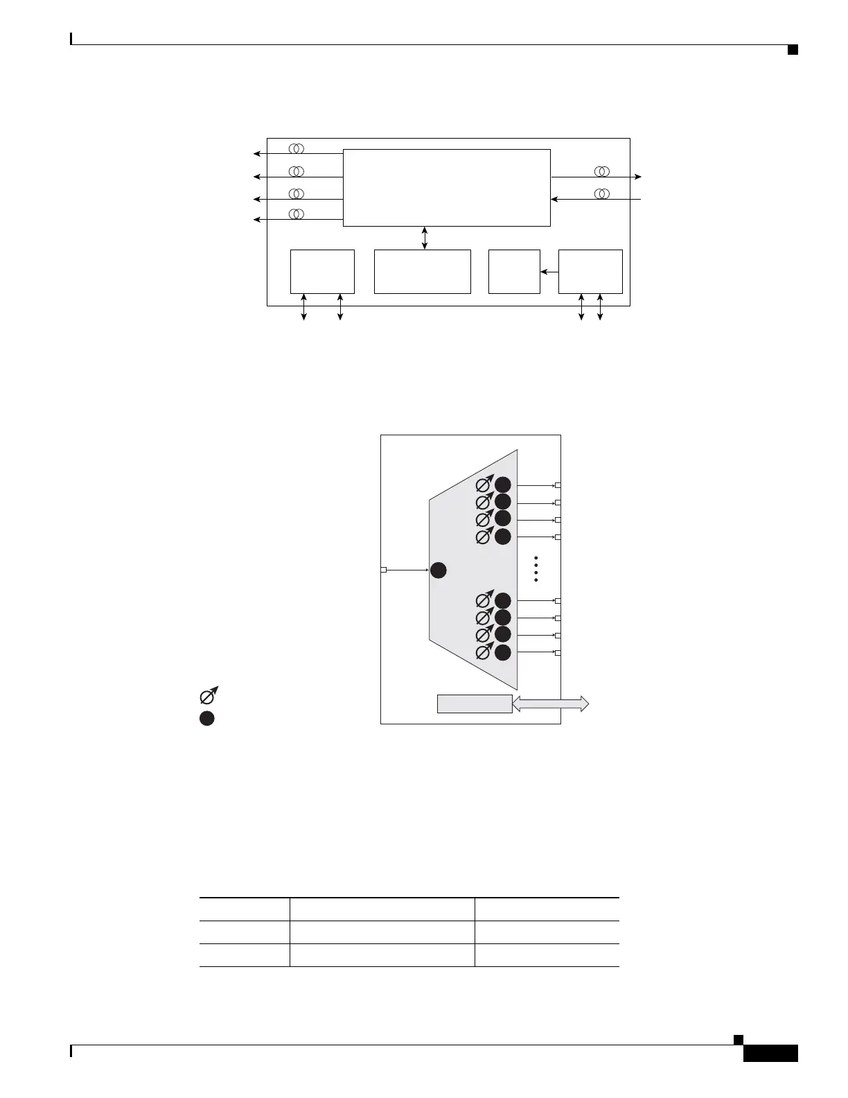
Figure 5-16 shows the 32DMX-O optical module functional block diagram.
Figure 5-16 32DMX-O Optical Module Functional Block Diagram
5.4.1 Power Monitoring
Physical photodiodes P1 through P33 monitor the power for the 32DMX-O card. The returned power
level values are calibrated to the ports as shown in Table 5-11.
Optical
module
30.3 to 36.6
8 CHS TX
38.1 to 44.5
8 CHS TX
46.1 to 52.5
8 CHS TX
54.1 to 60.6
8 CHS TX
96480
Processor
MON
COM RX
FPGA
For SCL Bus
management
SCL Bus
TCCi M
SCL Bus
TCCi P
DC/DC
Power supply
Input filters
BAT A&B
98302
1
32
Control
Control
interface
Physical photodiode
Variable optical attenuator
COM RX DROP TX
P32
P31
P30
P29
P4
P3
P2
P1
P
P33
Table 5-11 32DMX-O Port Calibration
Photodiode CTC Type Name Calibrated to Port
P1–P32 DROP DROP TX
P33 INPUT COM COM RX

 Loading...


