8-52
Cisco ONS 15454 DWDM Reference Manual, R8.5
78-18343-02
Chapter 8 Transponder and Muxponder Cards
8.10 MXP_MR_10DME_C and MXP_MR_10DME_L Cards
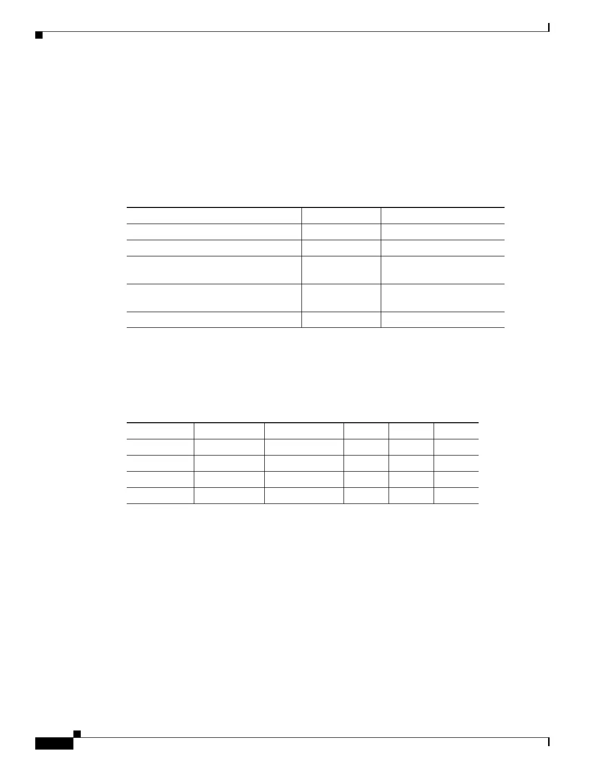
Table 8-27 shows the input data rate for each client interface, and the encapsulation method. The current
version of the GFP-T G.7041 supports transparent mapping of 8B/10B block-coded protocols, including
Gigabit Ethernet, Fibre Channel, ISC, and FICON.
In addition to the GFP mapping, 1-Gbps traffic on Port 1 or 2 of the high-speed SERDES is mapped to
an STS-24c channel. If two 1-Gbps client signals are present at Port 1 and Port 2 of the high-speed
SERDES, the Port 1 signal is mapped into the first STS-24c channel and the Port 2 signal into the second
STS-24c channel. The two channels are then mapped into an OC-48 trunk channel.
There are two FPGAs on each MXP_MR_10DME_C and MXP_MR_10DME_L, and a group of four
ports is mapped to each FPGA. Group 1 consists of Ports 1 through 4, and Group 2 consists of Ports 5
through 8. Table 8-28 shows some of the mix and match possibilities on the various client data rates for
Ports 1 through 4, and Ports 5 through 8. An X indicates that the data rate is supported in that port.
GFP-T PM is available through RMON and trunk PM is managed according to Telcordia GR-253-CORE
and ITU G.783/826. Client PM is achieved through RMON for FC and GE.
A buffer-to-buffer credit management scheme provides FC flow control. With this feature enabled, a port
indicates the number of frames that can be sent to it (its buffer credit), before the sender is required to
stop transmitting and wait for the receipt of a “ready” indication The MXP_MR_10DME_C and
MXP_MR_10DME_L cards support FC credit-based flow control with a buffer-to-buffer credit
extension of up to 1600 km (994.1 miles) for 1G FC, up to 800 km (497.1 miles) for 2G FC, or up to
400 km (248.5 miles) for 4G FC. The feature can be enabled or disabled.
The MXP_MR_10DME_C and MXP_MR_10DME_L cards feature a 1550-nm laser for the trunk/line
port and a 1310-nm or 850-nm laser (depending on the SFP) for the client ports. The cards contains eight
12.5 degree downward tilt SFP modules for the client interfaces. For optical termination, each SFP uses
two LC connectors, which are labeled TX and RX on the faceplate. The trunk port is a dual-LC connector
with a 45 degree downward angle.
Table 8-27 MXP_MR_10DME_C and MXP_MR_10DME_L Client Interface Data Rates and
Encapsulation
Client Interface Input Data Rate GFP-T G.7041 Encapsulation
2G FC 2.125 Gbps Yes
1G FC 1.06 Gbps Yes
2G FICON/2G ISC-Compatible (ISC-1)/
2G ISC-Peer (ISC-3)
2.125 Gbps Yes
1G FICON/1G ISC-Compatible (ISC-1)/
1G ISC-Peer (ISC-3)
1.06 Gbps Yes
Gigabit Ethernet 1.25 Gbps Yes
Table 8-28 Supported Client Data Rates for Ports 1 through 4 and Ports 5 through 8
Port (Group 1) Port (Group 2) Gigabit Ethernet 1G FC 2G FC 4G FC
15 X XXX
26 X X——
37 X XX—
48 X X——

 Loading...


