5-14
Cisco ONS 15454 DWDM Reference Manual, R8.5
78-18343-02
Chapter 5 Multiplexer and Demultiplexer Cards
5.3.1 Channel Plan
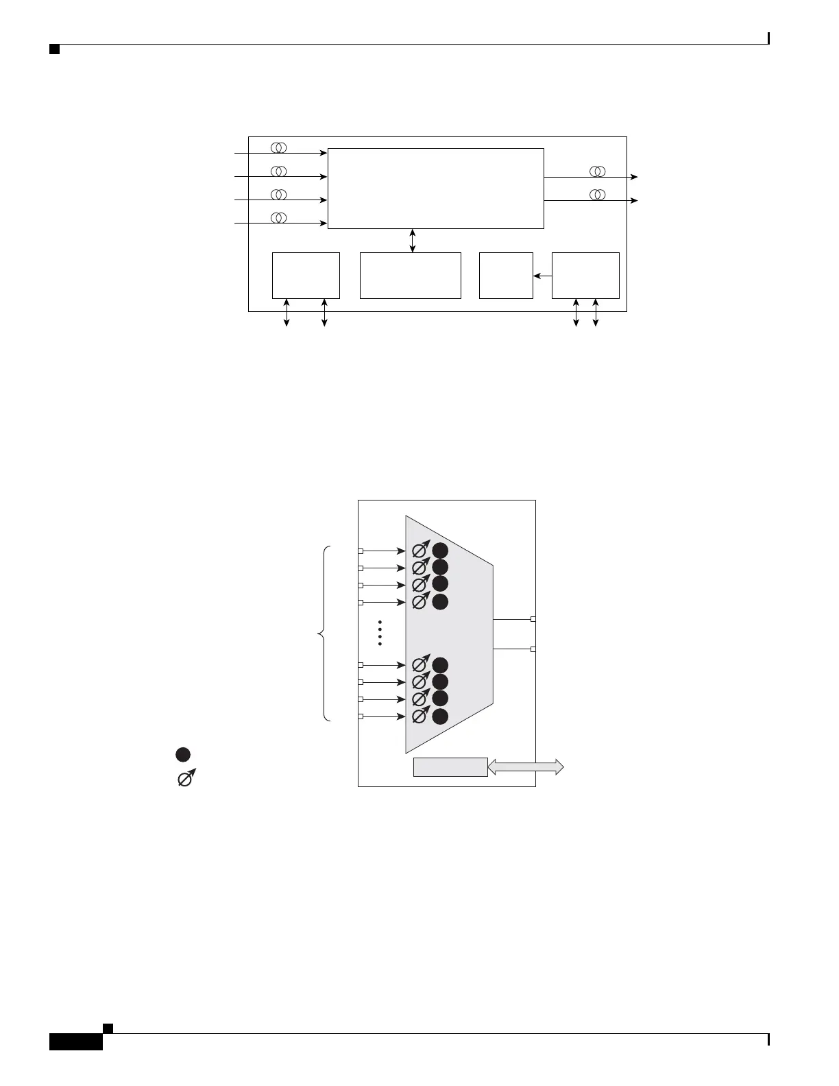
Figure 5-12 32MUX-O Block Diagram
The 32MUX-O card has four receive connectors that accept multifiber push-on (MPO) cables on its front
panel for the client input interfaces. MPO cables break out into eight separate cables. The 32MUX-O
card also has two LC-PC-II optical connectors, one for the main output and the other for the monitor port.
Figure 5-13 shows the 32MUX-O optical module functional block diagram.
Figure 5-13 32MUX-O Optical Module Functional Block Diagram
5.3.1 Channel Plan
The 32MUX-O is typically used in hub nodes and provides the multiplexing of 32 channels, spaced at
100 GHz, into one fiber before their amplification and transmission along the line. The channel plan is
shown in Table 5-8.
Optical
module
30.3 to 36.6
8 CHS RX
38.1 to 44.5
8 CHS RX
46.1 to 52.5
8 CHS RX
54.1 to 60.6
8 CHS RX
134413
Processor
MON
COM TX
FPGA
For SCL Bus
management
SCL Bus
TCCi M
SCL Bus
TCCi P
DC/DC
Power supply
Input filters
BAT A&B
98301
1
32
Control
Control
interface
Physical photodiode
Variable optical attenuator
MON
COM TX
Inputs
P32
P31
P30
P29
P4
P3
P2
P1
P

 Loading...


