4-29
Cisco ONS 15454 DWDM Reference Manual, R8.5
78-18343-02
Chapter 4 Optical Amplifier Cards
4.8.4 OPT-AMP-17-C Power Monitoring
Note When the OPT-AMP-17-C operates as a booster amplifier, APC does not control its gain.
4.8.4 OPT-AMP-17-C Power Monitoring
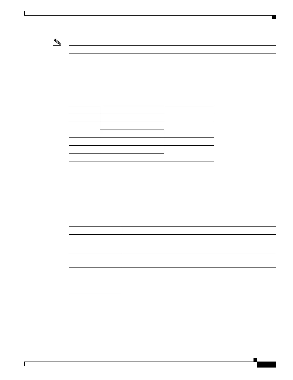
Physical photodiodes P1, P2, P3, P4, and P5 monitor power for the OPT-AMP-17-C card. Table 4-13
shows the returned power level values calibrated to each port.
For information on the associated TL1 AIDs for the optical power monitoring points, refer the “CTC
Port Numbers and TL1 Aids” section in Cisco ONS SONET TL1 Command Guide, Release 8.5.
4.8.5 OPT-AMP-17-C Card-Level Indicators
Table 4-14 shows the three card-level LEDs on the OPT-AMP-17-C card.
4.8.6 OPT-AMP-17-C Port-Level Indicators
You can determine the status of the card ports using the LCD screen on the ONS 15454 fan-tray
assembly. Use the LCD to view the status of any port or card slot; the screen displays the number and
severity of alarms for a given port or slot.
Table 4-13 OPT-AMP-17-C Port Calibration
Photodiode CTC Type Name Calibrated to Port
P1 Input COM COM RX
P2 Output Line (Total Output) LINE TX
Output Line (Signal Output)
P5 Output OSC-RX OSC-RX
P3 Output COM LINE RX
P4 Output OSC-TX
Table 4-14 OPT-AMP-17-C Card-Level Indicators
Card-Level Indicators Description
Red FAIL LED The red FAIL LED indicates that the card’s processor is not ready or that an
internal hardware failure occurred. Replace the card if the red FAIL LED
persists.
Green ACT LED The green ACT LED indicates that the OPT-AMP-17-C is carrying traffic or
is traffic-ready.
Amber SF LED The amber SF LED indicates a signal failure or condition such as LOS on
one or more of the card’s ports. The amber SF LED also turns on when the
transmit and receive fibers are incorrectly connected. When the fibers are
properly connected, the light turns off.

 Loading...


