1-12
Cisco ONS 15454 DWDM Reference Manual, R8.5
78-18343-02
Chapter 1 Shelf Assembly Hardware
1.4.1 FlexLayer Modules
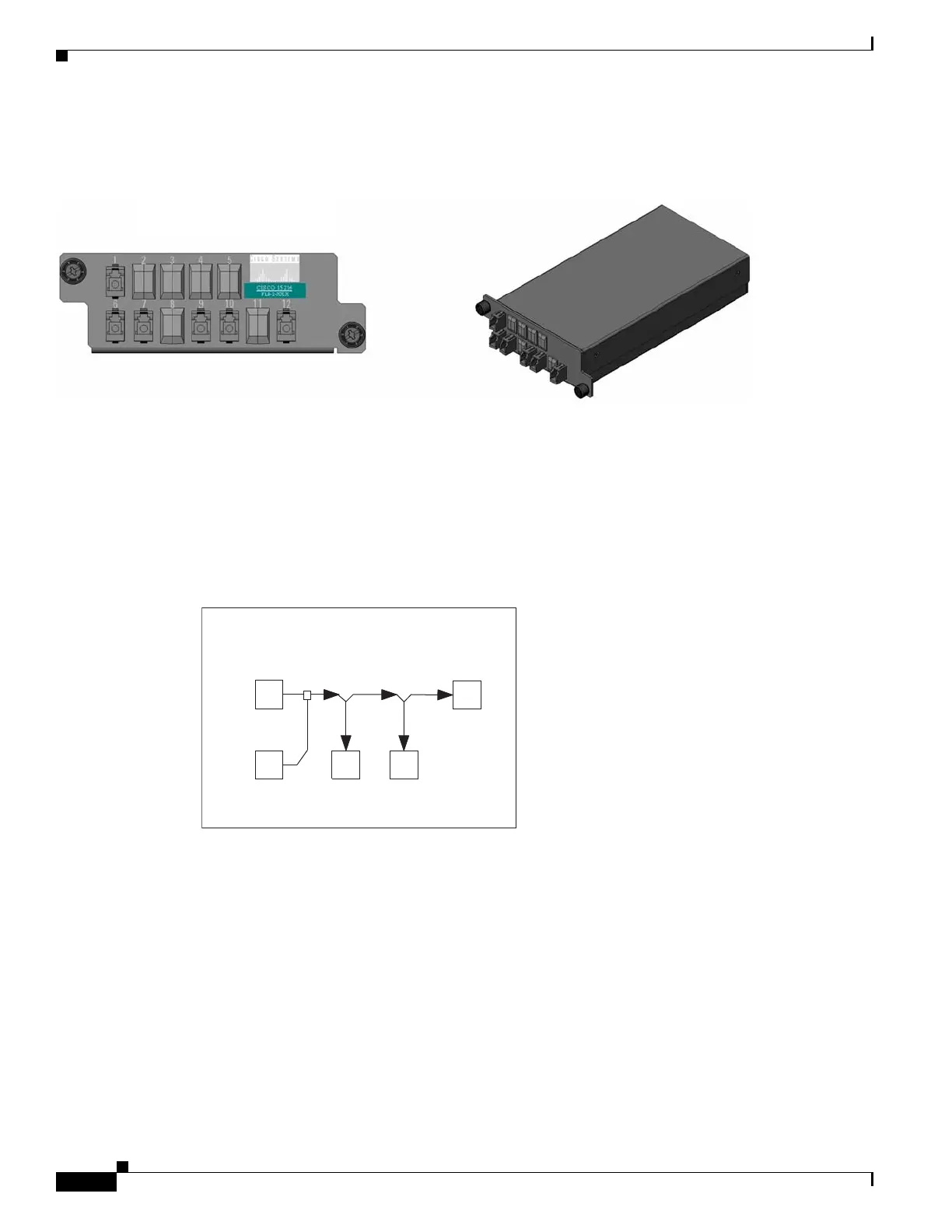
Figure 1-7 shows the physical appearance of the ONS 15454 two-channel add/drop FlexLayer module.
Figure 1-7 ONS 15454 Two-Channel Optical Add/Drop FlexLayer Module
Labels are provided to show how the module ports are mapped. It is the end user’s responsibility to label
the module for its intended use (drop or add component).
Figure 1-8 shows how the connectors are mapped and labeled on the front panel when the component is
used as a drop component. The COM-RX is mapped to Port 1, the COM-TX is mapped to Port 12, and
the two dropped channel TX ports are mapped to Ports 9 and 10. The two-percent tap MON port is
mapped to Port 6. Port 7 is not active.
Figure 1-8 Two-Channel Drop Component Connector Mapping and Labeling
Figure 1-9 shows how the connectors are mapped and labeled in the front panel when the component is
used as an add component. The COM-TX is mapped to Port 1, the COM-RX is mapped to Port 12, and
the added channels are mapped to the two RX Ports 9 and 10. The two-percent tap MON port is mapped
to Port 7. Port 6 is not active.
1
6 9 10
2 Channel Drop Module 15216-FLB-2-XX.X
MON
15XX.XX
TX
15XX.XX
TX
COM-RX
2% TAP
12
COM-TX
90949

 Loading...


