1-11
Cisco ONS 15454 DWDM Reference Manual, R8.5
78-18343-02
Chapter 1 Shelf Assembly Hardware
1.4.1 FlexLayer Modules
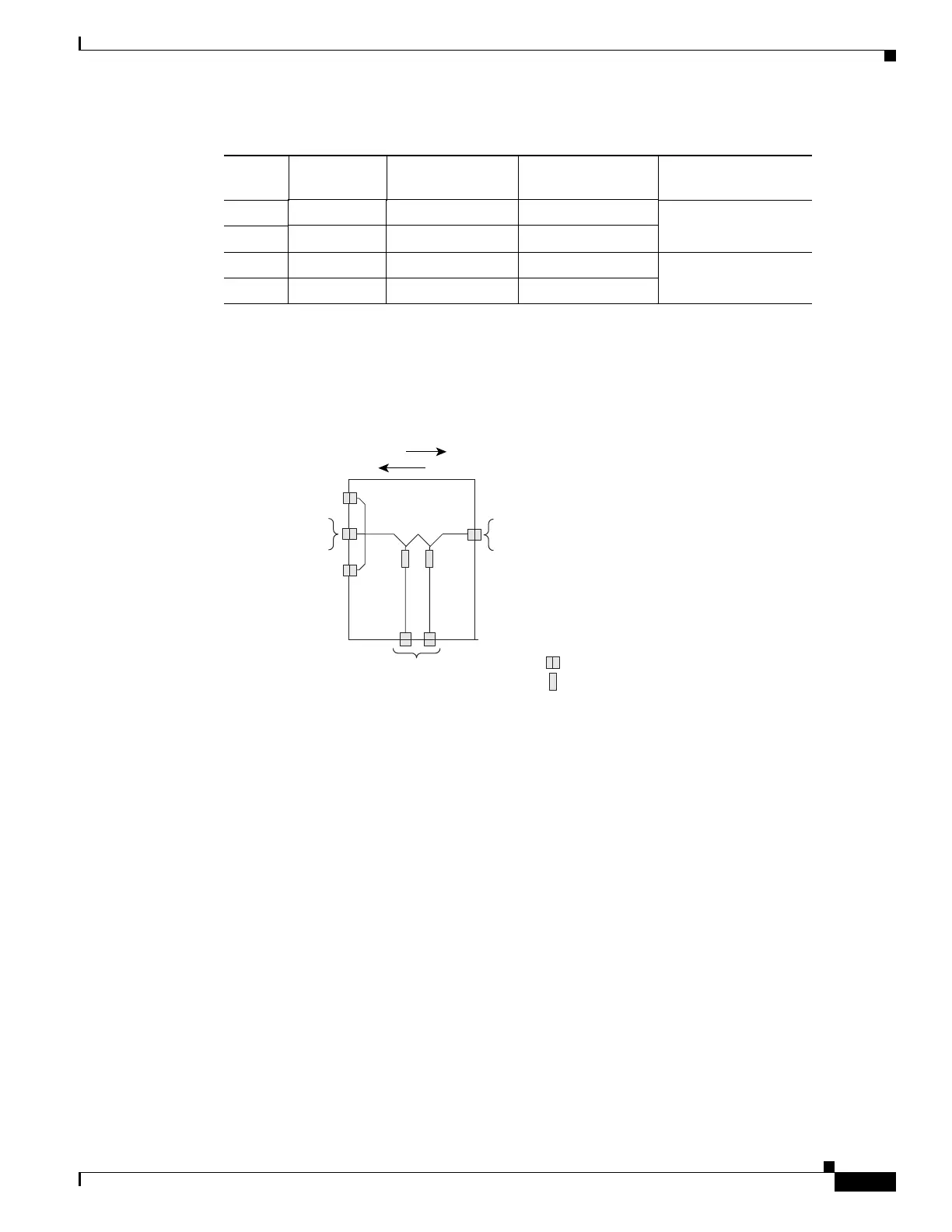
Figure 1-6 shows the module functional block diagram. In Figure 1-6, the signal flows from left to right
when the card is used as a drop component and from right to left when the module is used as an add
component.
Figure 1-6 Two-Channel Add/Drop FlexLayer Module Block Diagram
When the module is used as a drop component, the wave-division multiplexing (WDM) composite signal
coming from the DROP-COM-RX port is filtered sequentially by two filters and the filtered channels are
dropped at the two DROP-CH-TX ports. The rest of the WDM composite signal is sent to the
DROP-COM-TX port. A two-percent tap coupler, DROP-MON, is used to monitor the input WDM
composite signal.
When the module is used as an add component, the added channels coming from the two ADD-CH-RX
ports are combined with the WDM composite signal coming from the ADD-COM-RX port. The
multiplexed WDM composite signal is sent to the ADD-COM-TX port. A two-percent tap coupler,
ADD-MON, is used to monitor the multiplexed WDM composite signal.
24 58.1 192.4 1558.17 15216-FLB-2-58.9=
23 58.9 192.3 1558.98
22 59.7 192.2 1559.79 15216-FLB-2-60.6=
21 60.6 192.1 1560.61
Table 1-1 ONS 15454 100-GHz Channel Plan (continued)
ITU Channel ID Frequency (THz) Wavelength (nm)
Two-Channel A/D
Flex Module
90947
DROP-MON
DROP-COM-RX
ADD-COM-TX
ADD-MON
DROP-COM-TX
ADD-COM-RX
Connector
Channel Filter
ADD CH-RX
DROP CH-TX
DROP
ADD

 Loading...


