2-11
Cisco ONS 15454 DWDM Reference Manual, R8.5
78-18343-02
Chapter 2 Common Control Cards
2.4.1 AIC-I Card-Level Indicators
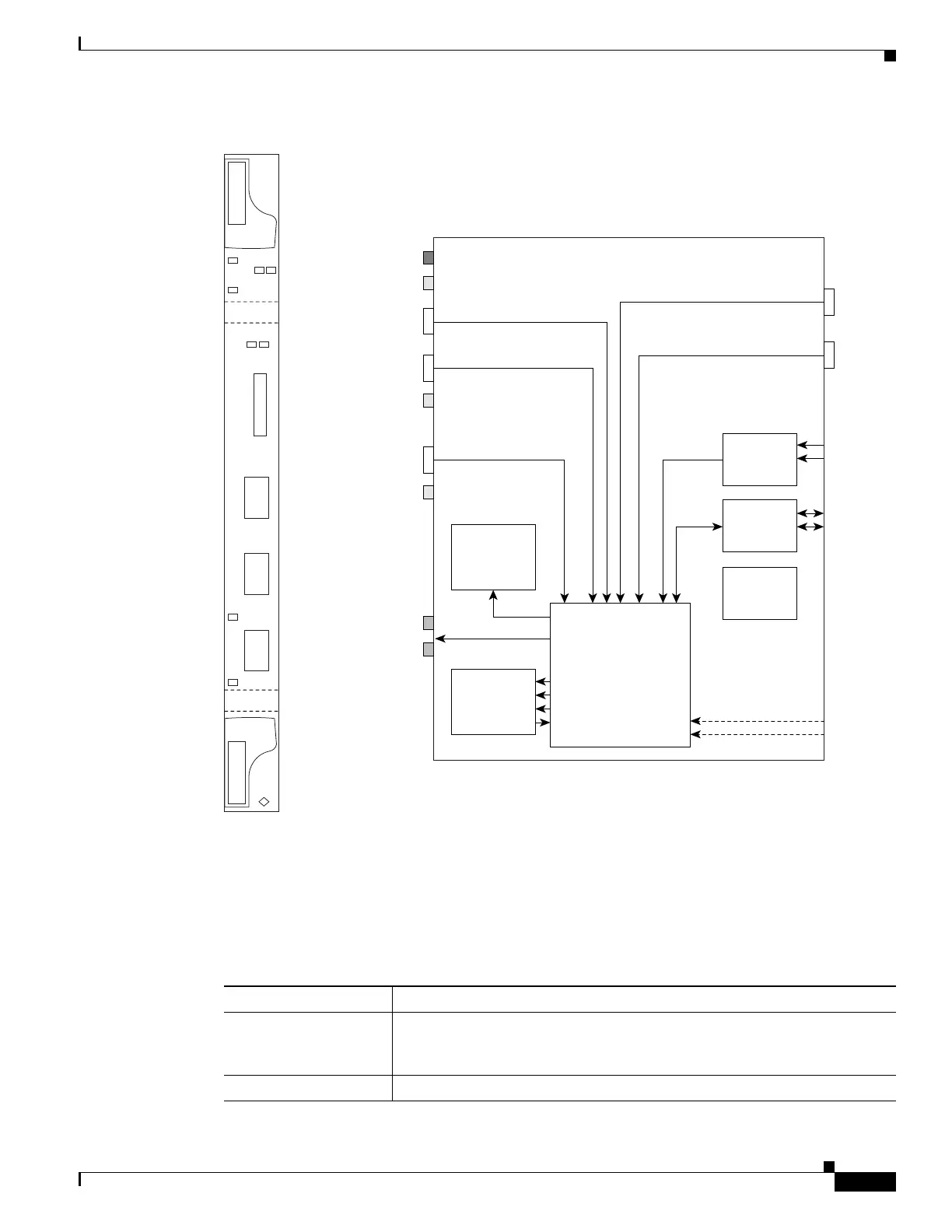
Figure 2-3 AIC-I Faceplate and Block Diagram
2.4.1 AIC-I Card-Level Indicators
Table 2-7 describes the eight card-level LEDs on the AIC-I card faceplate.
AIC-I
Fail
Express orderwire
Local orderwire
EEPROM
LED x2
AIC-I FPGA
SCL links
4 x
IN/OUT
Power
Monitoring
12/16 x IN
Ringer
Act
Ring
Ring
Input
Output
78828
FAIL
ACT
ACC
INPUT/OUTPUT
EOW
LOW
RING
AIC-1
(DTMF)
(DTMF)
UDC-A
UDC-B
DCC-A
DCC-B
ACC
PWR
A
B
RING
DCC-B
DCC-A
UDC-B
UDC-A
Table 2-7 AIC-I Card-Level Indicators
Card-Level LEDs Description
Red FAIL LED Indicates that the card’s processor is not ready. The FAIL LED is on during
reset and flashes during the boot process. Replace the card if the red FAIL
LED persists.
Green ACT LED Indicates the AIC-I card is provisioned for operation.

 Loading...


