8-19
Cisco ONS 15454 DWDM Reference Manual, R8.5
78-18343-02
Chapter 8 Transponder and Muxponder Cards
8.5.7 Client-to-Trunk Mapping
8.5.7 Client-to-Trunk Mapping
The TXP_MR_10E_C and TXP_MR_10E_L cards can perform ODU2-to-OCh mapping, which allows
operators to provision data payloads in a standard way across 10-Gbps optical links.
Digital wrappers that define client side interfaces are called ODU2 entities in ITU-T G.709. Digital
wrappers that define trunk side interfaces are called OCh in ITU-T G.709. ODU2 digital wrappers can
include G-MPLS signaling extensions to ITU-T G.709 (such as LSP and G-PID values) to define client
interfaces and payload protocols.
8.5.8 Automatic Laser Shutdown
The ALS procedure is supported on both client and trunk interfaces. On the client interface, ALS is
compliant with ITU-T G.664 (6/99). On the data application and trunk interface, the switch on and off
pulse duration is greater than 60 seconds. The on and off pulse duration is user-configurable. For details
regarding ALS provisioning for the TXP_MR_10E_C and TXP_MR_10E_L cards, refer to the
Cisco ONS 15454 DWDM Procedure Guide.
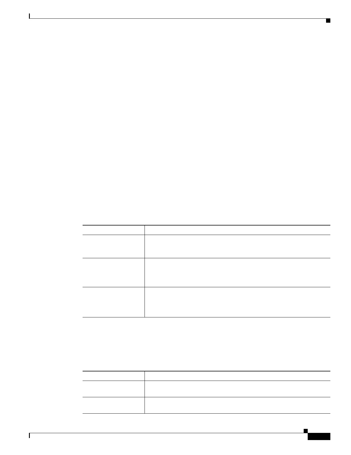
8.5.9 TXP_MR_10E_C and TXP_MR_10E_L Card-Level Indicators
Table 8-7 lists the three card-level LEDs on the TXP_MR_10E_C and TXP_MR_10E_L cards.
8.5.10 TXP_MR_10E_C and TXP_MR_10E_L Port-Level Indicators
Table 8-8 lists the two port-level LEDs in the TXP_MR_10E_C and TXP_MR_10E_L cards.
Table 8-7 TXP_MR_10E _C and TXP_MR_10E_L Card-Level Indicators
Card-Level LED Description
Red FAIL LED The red FAIL LED indicates that the card’s processor is not ready. This LED
is on during reset. The FAIL LED flashes during the boot process. Replace
the card if the red FAIL LED persists.
ACT/STBY LED
Green (Active)
Amber (Standby)
If the ACT/STBY LED is green, the card is operational (one or both ports
active) and ready to carry traffic. If the ACT/STBY LED is amber, the card
is operational and in standby (protect) mode.
Amber SF LED The amber SF LED indicates a signal failure or condition such as LOS, LOF,
or high BERs on one or more of the card’s ports. The amber SF LED is also
on if the transmit and receive fibers are incorrectly connected. If the fibers
are properly connected and the link is working, the light turns off.
Table 8-8 TXP_MR_10E_C and TXP_MR_10E_L Port-Level Indicators
Port-Level LED Description
Green Client LED The green Client LED indicates that the client port is in service and that it is
receiving a recognized signal.
Green DWDM LED The green DWDM LED indicates that the DWDM port is in service and that
it is receiving a recognized signal.

 Loading...


