2-22
Cisco ONS 15454 DWDM Reference Manual, R8.5
78-18343-02
Chapter 2 Common Control Cards
2.6.2 MIC-C/T/P FMEC
• Connection for one of the two possible redundant power supply inputs
• Connection for two serial ports for local craft/modem (for future use)
• Connection for one LAN port
• Connection for two system timing inputs
• Connection for two system timing outputs
• Storage of manufacturing and inventory data
For proper system operation, both the MIC-A/P and MIC-C/T/P FMECs must be installed in the shelf.
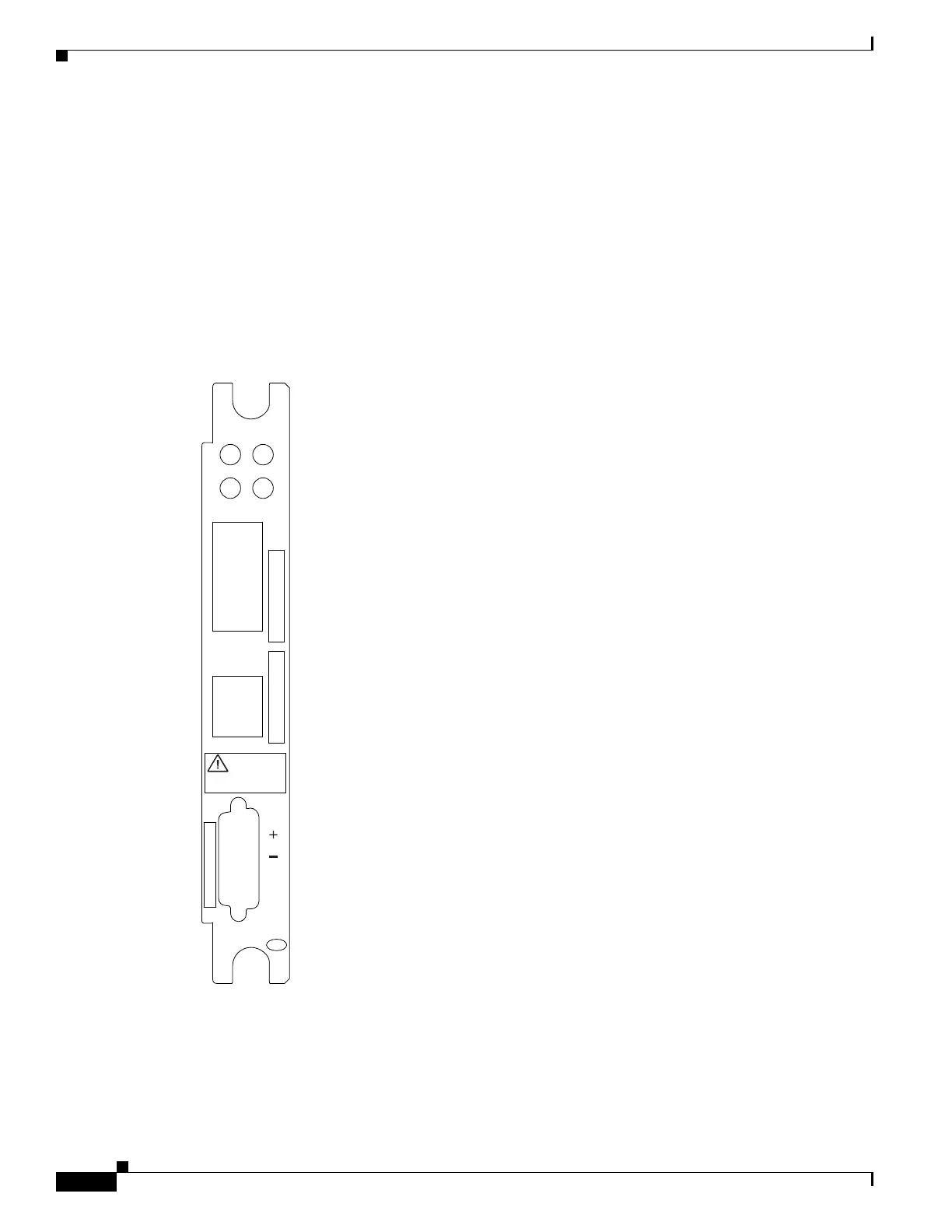
Figure 2-8 shows the MIC-C/T/P FMEC faceplate.
Figure 2-8 MIC-C/T/P Faceplate
Figure 2-9 shows a block diagram of the MIC-C/T/P.
MIC-C/T/P
CLEI CODE BARCODE
POWER RATING
GND
BATTERY A
TIMING A
IN TIMING B OUT
CAUTION
TIGHTEN THE FACEPLATETIGHTEN THE FACEPLATE
SCREWS WITH 1.0 NM TORQUESCREWS WITH 1.0 NM TORQUE
271306
LAN
AUX
TERM
ACT
LINK

 Loading...


