6-23
Cisco ONS 15454 DWDM Reference Manual, R8.5
78-18343-02
Chapter 6 Optical Add/Drop Cards
6.6.2 AD-1B-xx.x Card-Level Indicators
For information on the associated TL1 AIDs for the optical power monitoring points, refer the “CTC
Port Numbers and TL1 Aids” section in Cisco ONS SONET TL1 Command Guide, Release 8.5.
6.6.2 AD-1B-xx.x Card-Level Indicators
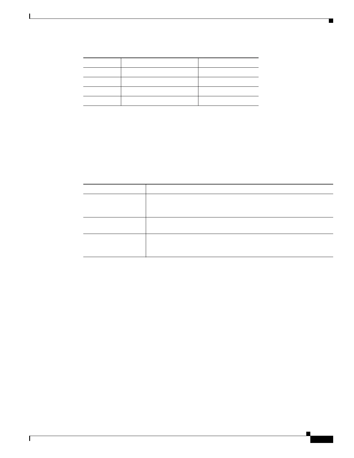
The AD-1B-xx.x card has three card-level LED indicators, described in Table 6-16.
6.6.3 AD-1B-xx.x Port-Level Indicators
You can find the status of the card port using the LCD screen on the ONS 15454 fan-tray assembly. Use
the LCD to view the status of any port or card slot; the screen displays the number and severity of alarms
for a given port or slot. The AD-1B-xx.x has six LC-PC-II optical ports: two for add/drop channel client
input and output, two for express channel input and output, and two for communication.
6.7 AD-4B-xx.x Card
The 4-Band OADM (AD-4B-xx.x) card passively adds or drops four bands of four adjacent
100-GHz-spaced channels. Two versions of this card with different part numbers—each version
designed for use with one set of bands—are used in the ONS 15454 DWDM system. The card
bidirectionally adds and drops in two different sections on the same card to manage signal flow in both
directions. This card can be used when there is asymmetric adding and dropping on each side (east or
west) of the node; a band can be added or dropped on one side but not on the other.
The AD1B-xx.x can be installed in Slots 1 to 6 and 12 to 17 and has the following features:
• Five software-controlled VOAs regulate the optical power flowing in the OADM paths.
P3 IN EXP EXP RX
P4 OUT EXP EXP TX
V1 IN COM COM RX
V2 OUT COM COM TX
Table 6-15 AD-1B-xx.x Port Calibration (continued)
Photodiode CTC Type Name Calibrated to Port
Table 6-16 AD-1B-xx.x Card-Level Indicators
Card-Level Indicators Description
Red FAIL LED The red FAIL LED indicates that the card’s processor is not ready or that
there is an internal hardware failure. Replace the card if the red FAIL LED
persists.
Green ACT LED The green ACT LED indicates that the AD-1B-xx.x card is carrying traffic
or is traffic-ready.
Amber SF LED The amber SF LED indicates a signal failure. The amber SF LED also
illuminates when the transmit and receive fibers are incorrectly connected.
When the fibers are properly connected, the light turns off.

 Loading...


