7-43
Cisco ONS 15454 DWDM Reference Manual, R8.5
78-18343-02
Chapter 7 Reconfigurable Optical Add/Drop Cards
7.8.4 40-DMX-CE Card Power Monitoring
For the ROADM functionality of other cards, see the description of that card in this chapter. For a
diagram of a typical ROADM configuration, see the “9.1.4 ROADM Node” section on page 9-12.
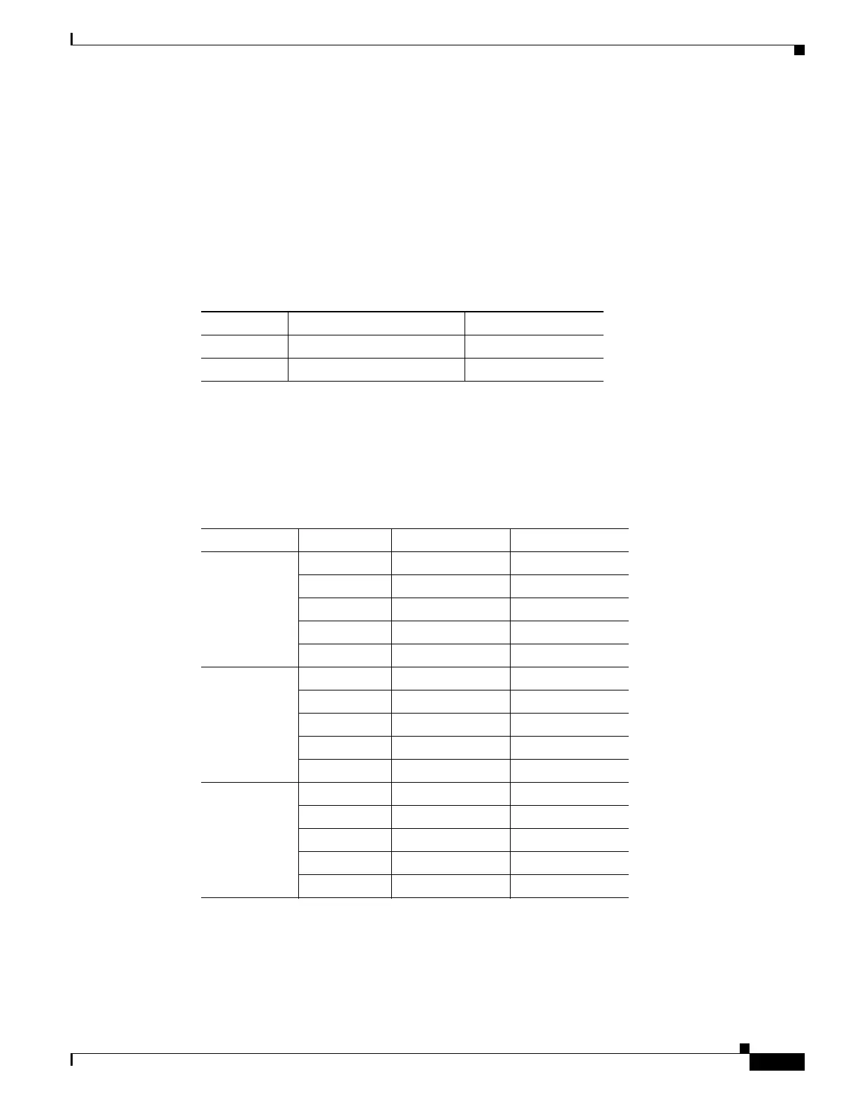
7.8.4 40-DMX-CE Card Power Monitoring
Physical photodiodes P1 through P40 monitor the power at the outputs of the 40-DMX-CE card. P41
monitors the total multiplexed power at the input, calibrated to the COM-RX port. Table 7-23 shows the
returned power level values calibrated to each port.
7.8.5 40-DMX-CE Card Channel Plan
Table 7-24 shows the 40 ITU-T 100-GHz-spaced, C band channels (wavelengths) that are demultiplexed
by the 40-DMX-CE card.
Table 7-23 40-DMX-CE Card Port Calibration
Photodiode CTC Type Name Calibrated to Port
P1–P40 DROP DROP TX
P41 INPUT COM COM RX
Table 7-24 40-DMX-CE Card Channel Plan
Band ID Channel Label Frequency (GHz) Wavelength (nm)
B30.7 30.7 195.85 1530.72
31.5 195.75 1531.51
32.3 195.65 1532.29
33.1 195.55 1533.07
33.9 195.45 1533.86
B34.6 34.6 195.35 1534.64
35.4 195.25 1535.43
36.2 195.15 1536.22
37.0 195.05 1537.00
37.8 194.95 1537.79
B38.6 38.6 194.85 1538.58
39.4 194.75 1539.37
40.1 194.65 1540.16
40.9 194.55 1540.95
41.8 194.45 1541.75

 Loading...


