1-48
Cisco ONS 15454 DWDM Reference Manual, R8.5
78-18343-02
Chapter 1 Shelf Assembly Hardware
1.12.4 Fiber Management Using the Fiber-Storage Tray
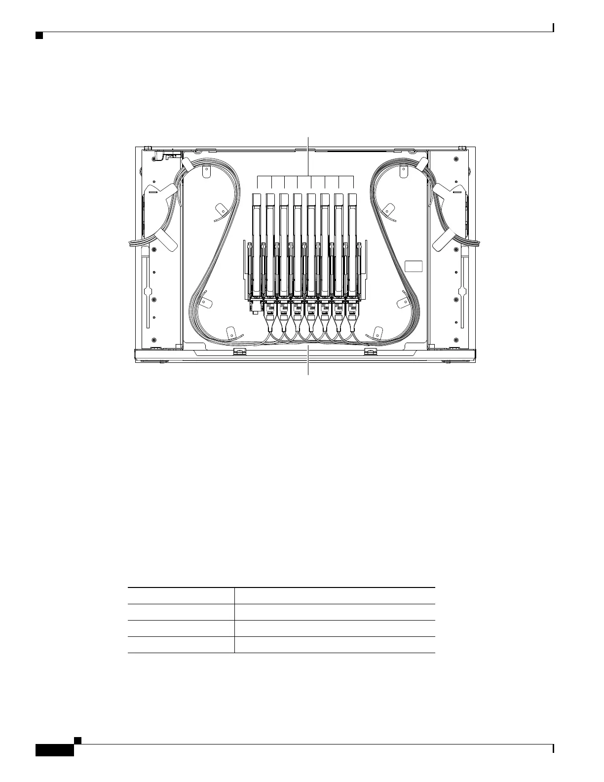
Figure 1-48 shows a fibered Y-cable module tray.
Figure 1-48 Y-Cable Module Tray
To ensure diversity of the fiber coming from different cards in the Y-cable scheme, one pair of fibers
(e.g. from the active transponder) should come out on the opposite side from the second pair of fibers
(e.g. standby transponder), according to local site practice.
1.12.4 Fiber Management Using the Fiber-Storage Tray
Cisco recommends installing at least one fiber-storage tray in multinode racks to facilitate fiber-optic
cable management for DWDM applications. This tray is usually used to store slack cable from cables
installed between cards within a single node. Refer to Figure 1-17 on page 1-20 for typical mounting
locations.
Table 1-11 provides the fiber capacity for each tray.
Figure 1-49 shows an example of a fiber-management tray with fiber-optic cables routed through it. You
can route cables around the cable rounders, entering and exiting from either side, as necessary. Route
fibers as necessary for your site configuration.
144678
LC-LC cables
Y cable modules
Table 1-11 Fiber-Storage Tray Capacity
Fiber Diameter Maximum Number of Fibers Exiting Each Side
0.6 inch (1.6 mm) 62
0.7 inch (2 mm) 48
0.11 inch (3 mm) 32

 Loading...


