Rockwell Automation Publication 2198-UM004D-EN-P - December 2022 295
Chapter 11 Motion Control in PR Mode
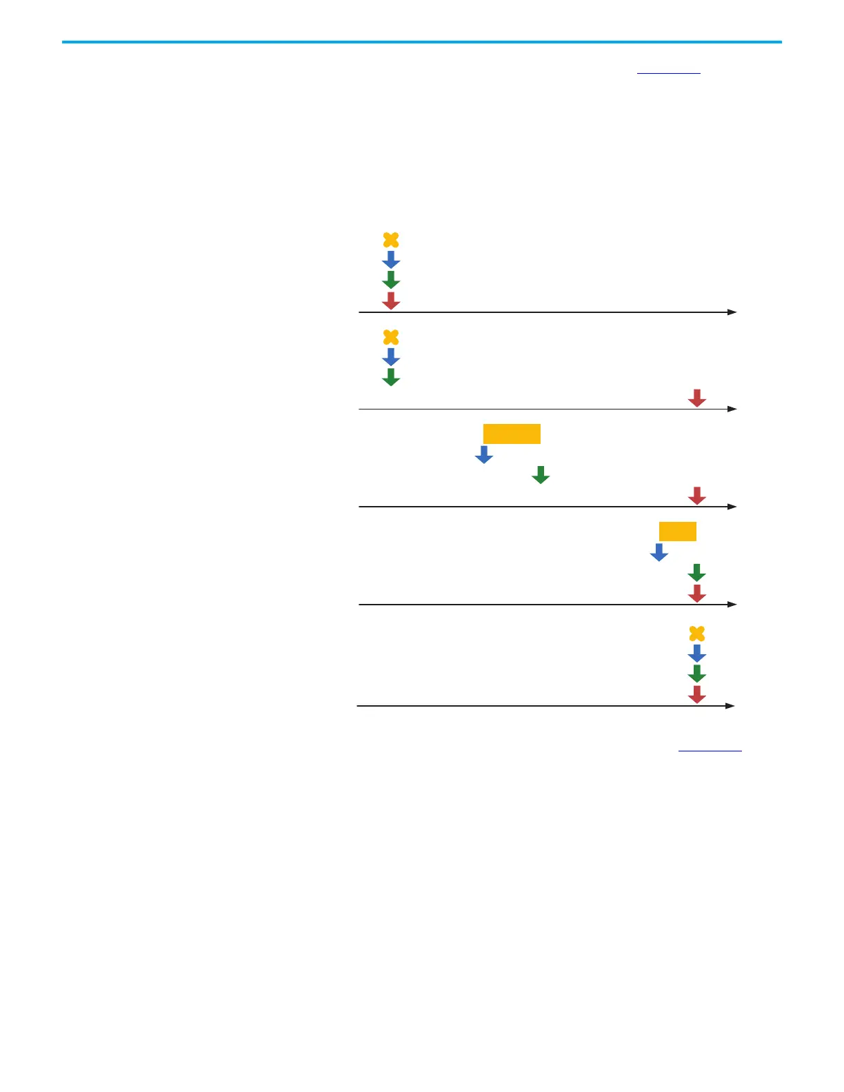
How these four monitoring variables work is shown in Figure 104. After the
drive sets a Position command, the drive sets the position of Cmd_E once the
target position data is acquired. The motor moves to the target position based
on the PR command setting. Cmd_O calculates the command position data in
each fixed cycle (1 ms) and sends it to the servo drive, where it is treated as a
dynamic command. Fb_PUU is the motor feedback position and Err_PUU is
the deviation of Cmd_O minus Fb_PUU.
Figure 104 - Timing Diagram of PR Mode Monitoring Variables
The detailed command behavior of each stage is illustrated in Figure 105.
Cmd_E is the endpoint specified by the command; this value is determined
once the PR command is triggered. Fb_PUU is the feedback position, which is
the motor actual position. For example, Cmd_O is the target of this command
section and Err_PUU is the deviation between target position and feedback
position.
Err_PUU
Before
command
issued
Fb_PUU
Cmd_O
Cmd_E
Err_PUU
Fb_PUU
Cmd_O
Cmd_E
Err_PUU
Fb_PUU
Cmd_O
Cmd_E
Err_PUU
Fb_PUU
Cmd_O
Cmd_E
Err_PUU
Fb_PUU
Cmd_O
Cmd_E
Command in
execution
Command
completed
Motor
positioned
After
command
issued

 Loading...


