Rockwell Automation Publication 2198-UM004D-EN-P - December 2022 389
Chapter 12 Motion Control Applications
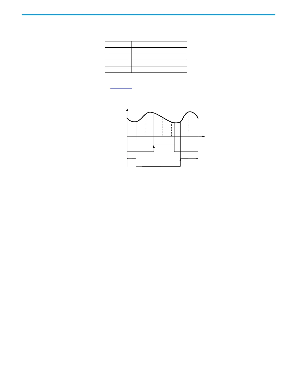
The following parameters define the function.
The relationship between DO.CAM_Area2 and the parameter values is shown
in Figure 197
. When E-CAM is not engaged, this signal is always off.
Figure 197 - Digital Output 2 - Engagement Timing
Table 122 - Relevant Parameters
Parameter Name
ID378 (P5.090) ECamDOCamArea1RisingEdgeAngle
ID379 (P5.091) ECamDOCamArea1FallingEdgeAngle
ID249 (P2.078) ECamDOCamArea2RisingEdgeAngle
ID250 (P2.079) ECamDOCamArea2FallingEdgeAngle
E-Cam position (PUU)
E-Cam angle ()
04590135180225 270
315
360
ID249 (P2.078) = 135
ID249 (P2.078) = 270
ID249 (P2.078)
ID249 (P2.078) > ID250 (P2.079)
ID250 (P2.079) = 240
ID250 (P2.079) = 45
ID250 (P2.079)
DO:0x1A
DO:0x1A
≤
E-CAM position (PUU)
E-CAM angle °

 Loading...


