Rockwell Automation Publication 2198-UM004D-EN-P - December 2022 401
Chapter 12 Motion Control Applications
You can use KNX5100C software to create electronic cam curves. Navigate to
Motion Control>E-CAM editor, shown in Figure 210
.
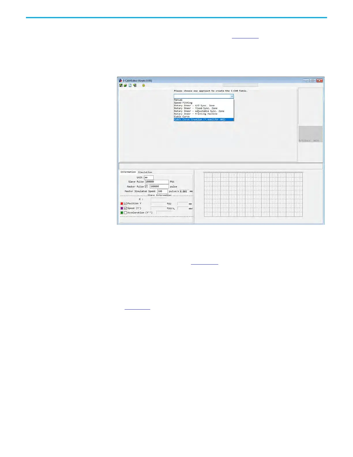
The E-CAM editor contains a wizard that uses 4 steps to complete the E-CAM
configuration. Step 1 is used to choose the approach to use for your E-CAM.
Figure 210 - E-CAM Edit Dialog Box
Manual
If the E-CAM table is already known, you can enter the points to complete the
cycle profile. As shown in Figure 209
, the E-CAM curve is created based on the
cam curve-to-edge distance corresponding to each angle of the mechanical
cam, which is relationship between the angle and the slave axis position. You
must use your master machine cycle profile as degrees. These values can be
normalized back into counts in the E-CAM editor Parameter Setting Step. The
KNX5100C software E-CAM table manual creation interface is shown in
Figure 211
. The following are the steps to manually create the table:
1. Set the number of E-CAM segments.
A single cam can be divided into up to a maximum of 720 segments (721
points). For a period of 360 degrees, every 0.5 degrees corresponds to a
slave axis position. The more points, the higher the resolution. To select
the most suitable number of segments, consider the resolution of the
curve and the resource usage of the data array.

 Loading...


