Rockwell Automation Publication 2198-UM004D-EN-P - December 2022 461
Appendix A Interconnect Diagrams
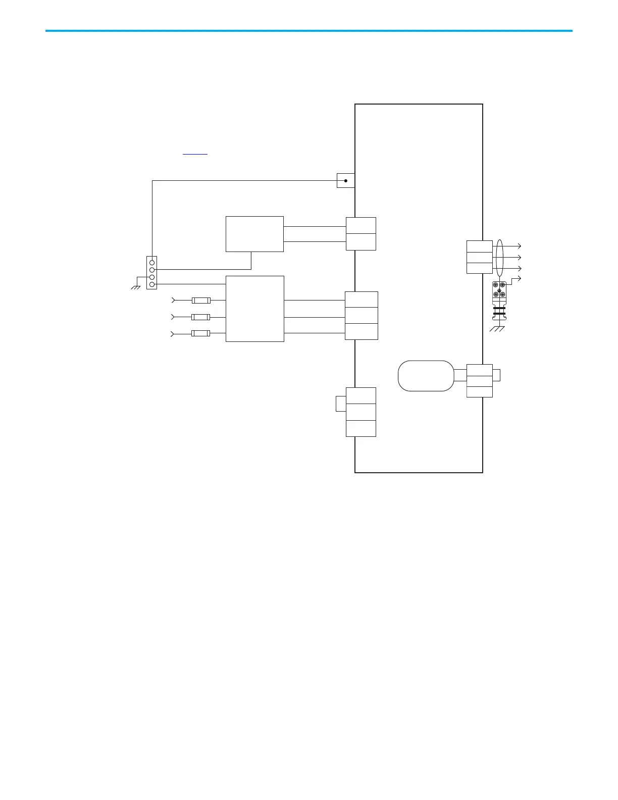
In this example, the 2198-E4004-ERS,2198-E4007-ERS, and 2198-E4015-ERS,
drives are wired for 480V three-phase operation.
Figure 241 - Kinetix 5100 Drive (480V three-phase input power)
U
V
W
L3
L2
L1
P1
P2
DC–
24V+
24V-
DC+
ESH
ISH
Three-phase AC Input
480V rms AC, 50/60 Hz
Notes 1, 5
Bonded Cabinet
Ground Bus *
Mains
AC Input Power
Connector
Circuit
Protection*
Motor Power
Connector
2198-E4004-ERS, 2198-E4007-ERS,
and 2198-E4015-ERS
Kinetix 5100 Servo Drives
* Indicates Customer Supplied Component
See table on page 457
for note information.
AC Line Filter
Note 6
Three-phase
Motor Power
Connections
Note 13
Ground Plate
Note 11
PE (mounting screw)
Note 12
Note 2
Control Input Power
Connector
Chassis
Customer Supplied
+24V DC
Power Supply *
Internal Shunt
Resistor
Passive Shunt
Connector
Note 4

 Loading...


