CMS32L051 User Manual |Chapter 5 Universal Timer Unit (Timer4)
www.mcu.com.cn 107 / 703
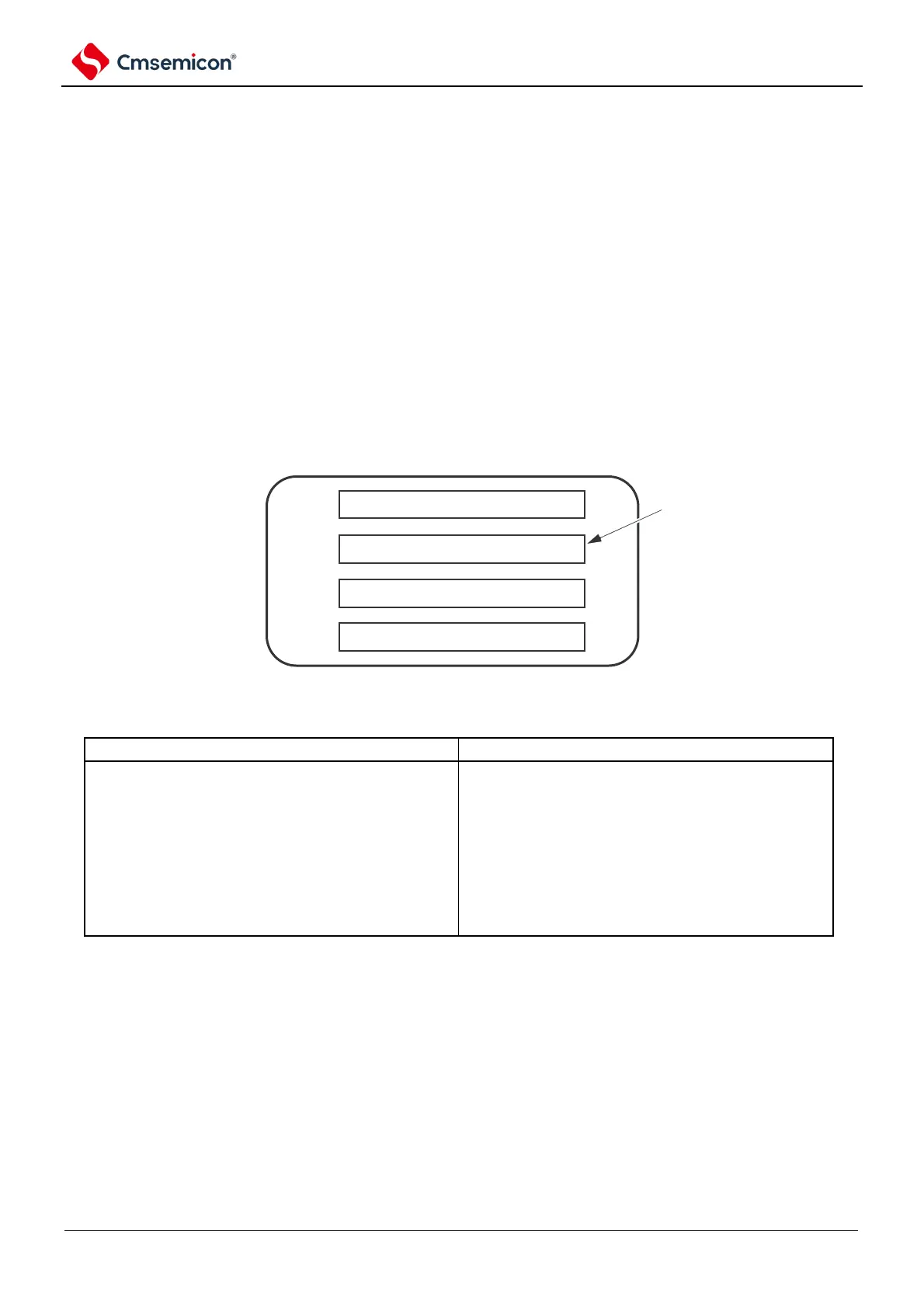
Channel 0
Channel 1
Channel 2
Chapter 5 Universal Timer Unit (Timer4)
This product is equipped with two universal timer units, each containing 4 channels.
Note:
1. The label m in the following part of this chapter represents the unit number, this product is equipped
with two universal timers Timer4, so m=0,1.
2. The label n in the following chapter represents the channel number (n=0~3 in this chapter).
3. The following contents of this chapter are mainly for 48-pin products.
Each general-purpose timer unit has four 16-bit timers.
Each 16-bit timer, called a channel, can be used as a separate timer or as a combination of multiple
channels as an advanced timer function.
Universal timer unit
16-bit timer
For details of each feature, please refer to the following table.
Independent channel operation function
Multi-channel linkage operation function
Interval timer ( to 5.8.1).
Single-trigger pulse output (refer to 5.9.1).
refer to 5.8.1).
PWM output (refer to 5.9.2).
External event counter (refer to 5.8.2).
Multiple PWM outputs (refer to 5.9.3).
refer to 5.8.3).
refer to 5.8.4).
signal (refer to 5.8.5).
Delay counter (refer to 5.8.6).
Channel 1 of unit 0 and 16-bit timers of channel 3 can be used as two 8-bit timers (high and low).
Channels 1 and 3 can be used as 8-bit timers as follows
Interval timer (high 8-bit and low 8-bit timer)/square wave output (limited to low 8-bit timer only).
External event counter (low 8-bit timer only).
Latency counter (low 8-bit timer only).