CMS32L051 User Manual |Chapter 17 Linkage Controller (EVENTC)
www.mcu.com.cn 610 / 703
17.4 Operation of EVENTC
The path used by the event signal generated by each peripheral function as an interrupt request for
the interrupt control circuit and the path used as an eventc event are independent of each other.
Therefore, each event signal is independent of interrupt control and can be used as an event signal for the
operation of peripheral functions of the event receiver.
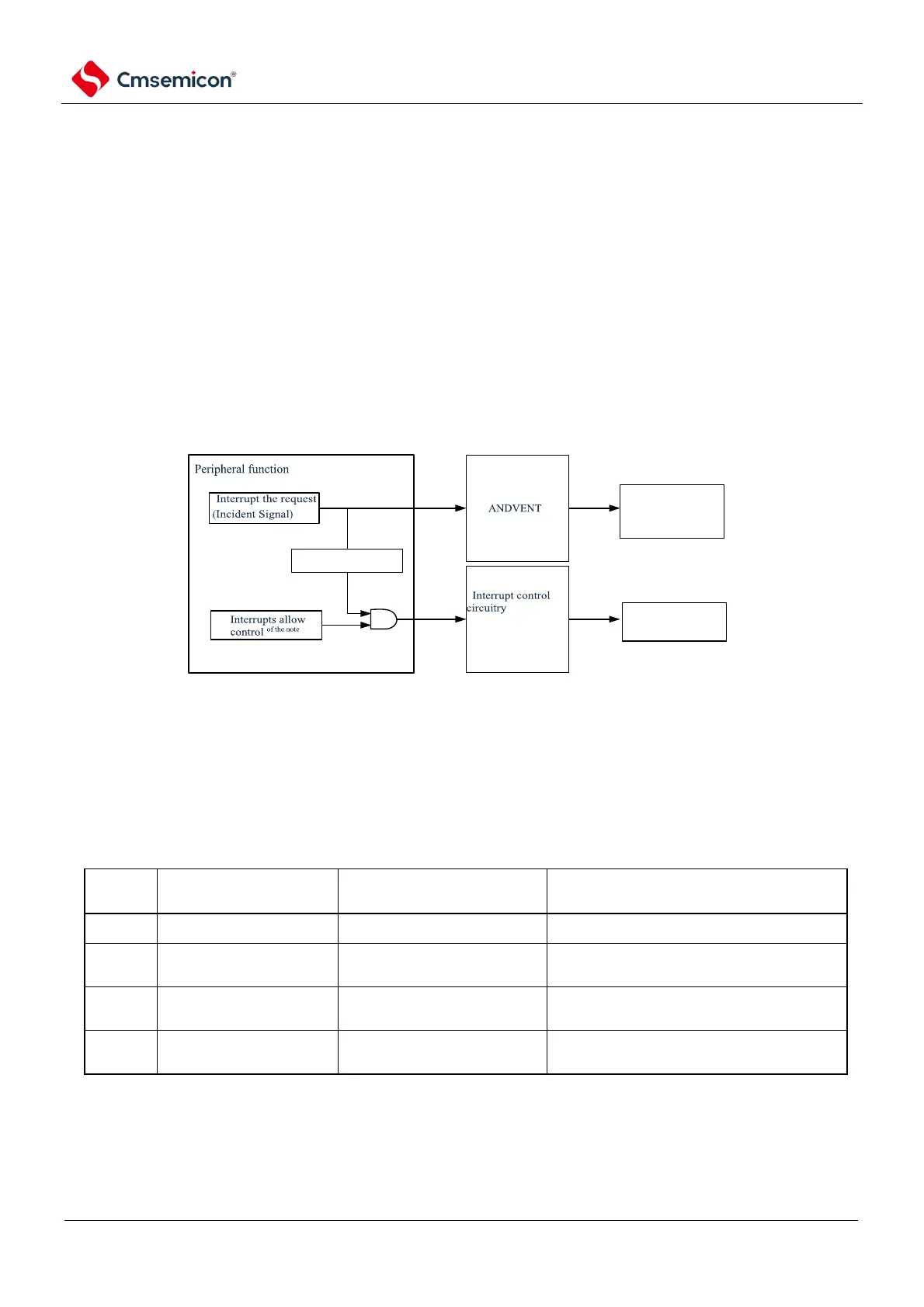
The relationship between interrupt handling and EVENTC is shown in Figure 17-3. This figure takes
the relationship between peripheral functions with interrupt request status flags and interrupt allow bits
(which control whether to allow or disable) as an example.
The peripheral function that accepts an event through EVENTC operates according to the operation of
the receiver peripheral function after receiving the event (refer to Table 17-3 Correspondence between the
setting value of ELSELRn register (n=00~14) and the operation when the link target peripheral function
accepts the event
Figure 17-3 The relationship between interrupt processing and EVENTC
Note Some peripheral features do not have this feature.
The response to the perimeter function that accepts the event is shown in Table 17-4.
Table 17-4 Response of the peripheral function of the received event