CMS32L051 User Manual |Chapter 5 Universal Timer Unit (Timer4)
www.mcu.com.cn 160 / 703
5.7 Control of timer input (TImn)
5.7.1 Structure of TImn pin input circuit
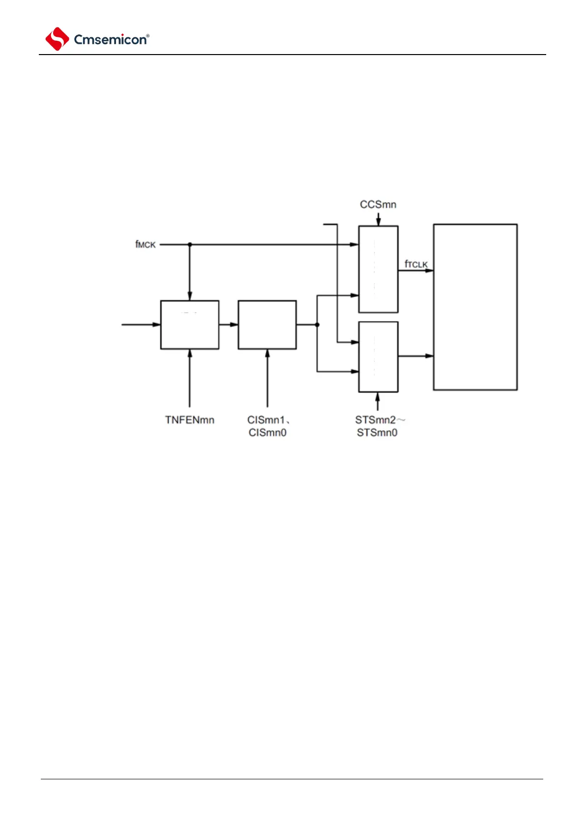
The signal from the timer input pin is input to the timer control circuit through the noise
filter and edge detection circuitry. For pins that need to be noise removed, the
corresponding pin noise filter must be set to active. The structure of the input circuit is
as follows.
Figure 5-40: Structure of input circuit