CMS32L051 User Manual |Chapter 6 Function of EPWM Output Control Circuit
www.mcu.com.cn 208 / 703
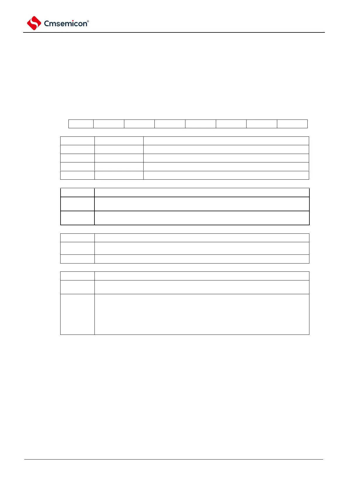
6.2.4 EPWM force truncated input selection register (EPWMSTC)
The EPWMSTC register makes the selection of the input source forced truncation.
The EPWMSTC register is set via 8-bit memory operation instructions.
After the reset signal is generated, the value of this register becomes 00H.
Figure 6-4 Format of EPWM force truncated input selection register (EPWMSTC)
Selection of truncation sources
Note 1, 3, 4
Source of force truncation/edge selection of force truncation output source
Note 1, 2
Rising edge: Output force truncation
Falling edge: Output force truncation released
Rising edge: Output force truncation released
Falling edge: Output force truncation
Output mode selection for forced truncation
Release timing selection for forced output truncation
After the release signal generated by hardware or software occurs, the
truncation is immediately released and the pulse output is restored.
After the release signal generated by hardware or software occurs, wait for the
following timing:
Select TO01 as the channel of the source clock: Truncation is released on the
rising edge of the next TO01, and the pulse output is restored
Select TO03 as the channel of the source clock: the cut-off is released on the
rising edge of the next TO03 and the pulse output is restored
Note 1: Set theN_EG at least three clocks apart after the I SC_SEL1 setting, and then set the C_SEL0 and S.
Note 2: Valid only when INTP0 input is selected.
Note 3: When using EVENTC to unenforce the cut-off, software dismiss must be selected (HS_SEL set to 1). There is
no restriction when using I NTP0 input.
Note 4: The effective width of the input selected INTP0 must be greater than one clock cycle.