CMS32L051 User Manual |Chapter 24 Security Features
www.mcu.com.cn 678 / 703
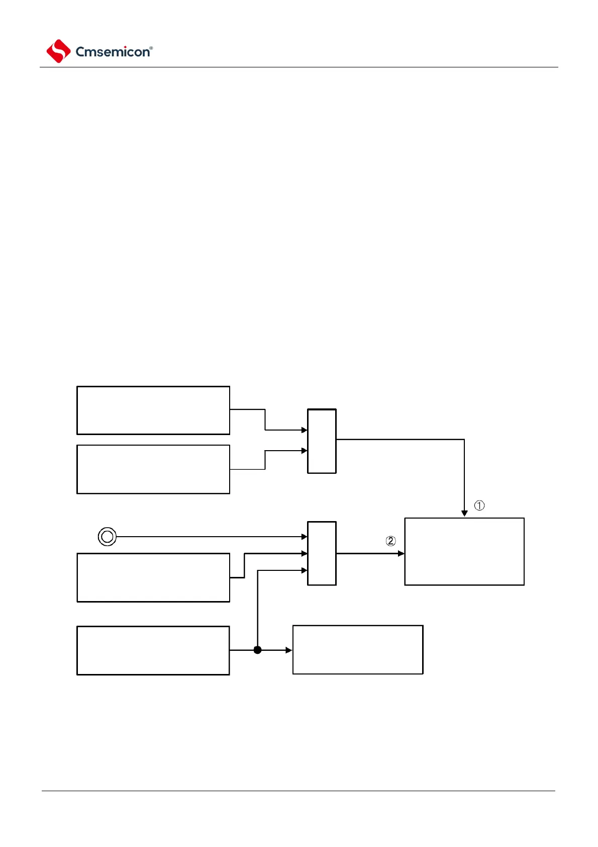
24.3.5 Frequency detection function
The IEC60730 standard requires confirmation of whether the oscillation frequency is normal.
The frequency detection function uses the clock frequency (f
CLK
) of the CPU/peripheral hardware and can
determine whether the ratio relationship between the two clocks is correct by measuring the Timer40 channel
1 input pulse.
However, if 1 clock or 2 clocks stop oscillating, the ratio of 2 clocks cannot be determined.
< clock to compare >
(1) Clock frequency of CPU/peripheral hardware (f
CLK
):
High speed internal oscillator clock (f
IH
).
High Speed System Clock (f
MX
).
(2) Timer40 channel 1 input:
Timer input for channel 1 (TI01).
Low-speed internal oscillator clock (f
IL
:
15kHz (TYP.))
Sub-System Clock (f
SUB
)
Note
Figure 24-10 Structure of frequency detection function
When the measurement result of the input pulse interval is an outlier, it can be judged as clock
frequency anomaly. For the measurement method of the input pulse interval, refer to 5.8.4
Note Only products with a built-in sub-system clock can be selected.
24.3.5.1 Timer input selection register 0 (TIS0)
Refer to Section 5.3.8 for a description of the registers.