CMS32L051 User Manual |Chapter 16 Enhanced DMA
www.mcu.com.cn 581 / 703
16.3.3 Vector table
Once the DMA is started, the control data is determined by reading the data from the vector table
allocated by each startup source, and the control data assigned to the DMA control data area is read.
The DMA boot source and vector addresses are shown in Table 16-5. Each startup source vector
table has 1 byte, holds the data from 00H to 17H, and selects 1 from 24 groups of control data Group
data. The upper 22 bits of the vector address are set by the DMABAR register, and the lower 10 bits are
assigned 00H to 17H for the corresponding startup source.
Note The DMAENi0~DMAENi7 bits must be 0 in the corresponding DMAENi (i=0~2) registers (Disable Startup) when
setting the starting address of the DMA control data area in the vector table.
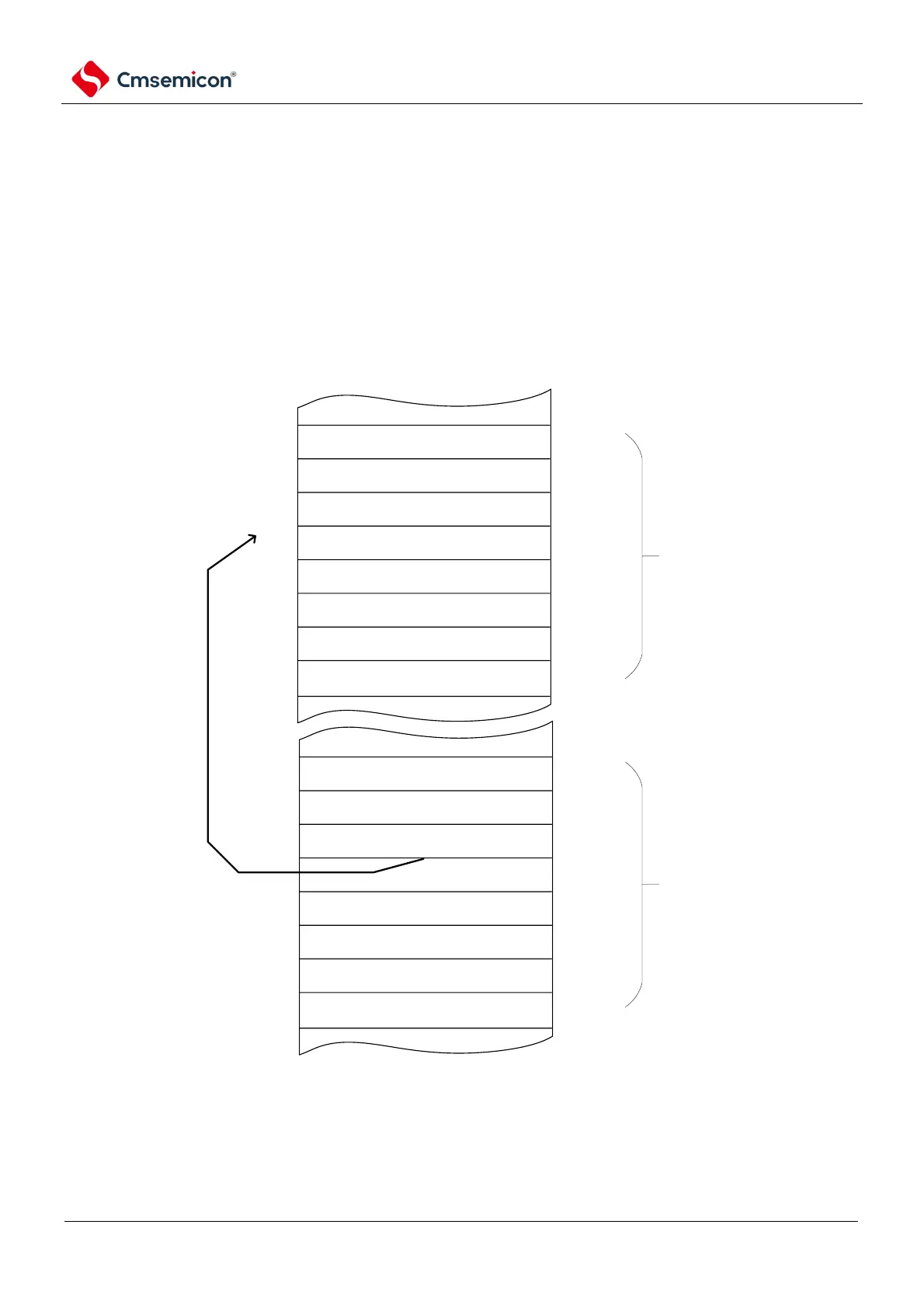
Figure 16-4 Starting address and vector table of control data
2000000H (example)
control data 23
control data 3
control data 20
control data 2
control data 1
control data 0
20000020H
20000030H
20000040H
20000050H
20000180H
20000190H
17H
03H
14H
02H
01H
00H
20000000H
20000001H
20000002H
20000003H
20000014H
20000017H
reserved
INTP0
INTP1
INTP2
Channel 3 of Timer 41
counting ends
Channel 10 of Timer 41
counting ends
DMA control data region
20000020H~2000019FH
(scenario when DMABAR
is20000000H)
DMA control data region
20000000H~20000017H
(scenario when DMABAR is
H
example) if channel 0 of
timer 40 count completion
DMA start source activated,
then read control data from
vector table value(180H)
corresponding control data
region 20000180H and start
transmitting.