CMS32L051 User Manual |Chapter 15 IrDA
www.mcu.com.cn 570 / 703
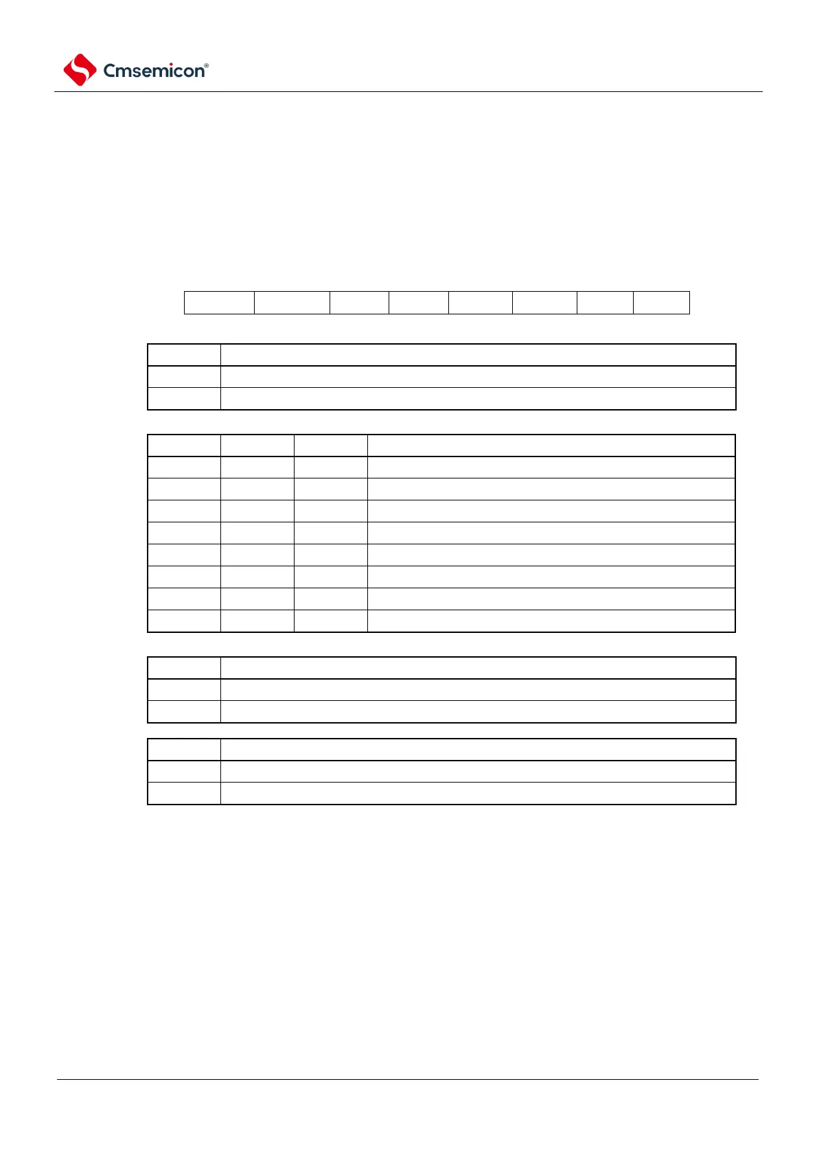
15.2.2 IrDA control register (IRCR)
This is the register that controls the IrDA function. Selects for polarity switching of received and
transmitted data, clock selection for IrDA, and switching of serial input/output pin functions (typically
serial and IrDA functions). The IRCR register is set via an 8-bit memory operation command. After the
reset signal is generated, the value of this register becomes 00H.
Figure 15-3 Format of IrDA Control Register (IRCR)
Address: 40044000H After reset: 00HR/W
Serial input/output pins are used as the usual serial function
The serial input/output pins are used as IrDA functions
Polarity switching of IrTxD data
IrTxD output of the transmitted data
Reverse the data sent for IrTxD output
Polarity switching of IrRxD data
Use the input data from the IrRxD pin as the receive data
The data after inverting the input data of the IrRxD pin is used as the received data
Note 1 You must set bit1 and bit0 to 0.
2. IRCKS [2:0] bits, IRTXINV bits, and IRRXINV bits can be set only when the IRE bit is 0.