CMS32L051 User Manual |Chapter 4 Clock Generation Circuit
www.mcu.com.cn 103 / 703
4.7.3 Operation description
4.7.3.1 Operation overview
The high-speed internal oscillation frequency correction function uses the subsystem clock (fSUB) as a
reference to generate a correction period, measure the frequency of high-speed internal oscillation, and
correct the frequency accuracy of high-speed internal oscillator in real time. Clock adjustment for the
repetition of the operation of the measurement phase and the frequency correction phase. The correction
calculus is performed during the frequency measurement phase, and the correction values that reflect the
results of the correction calculus are saved during the frequency correction phase.
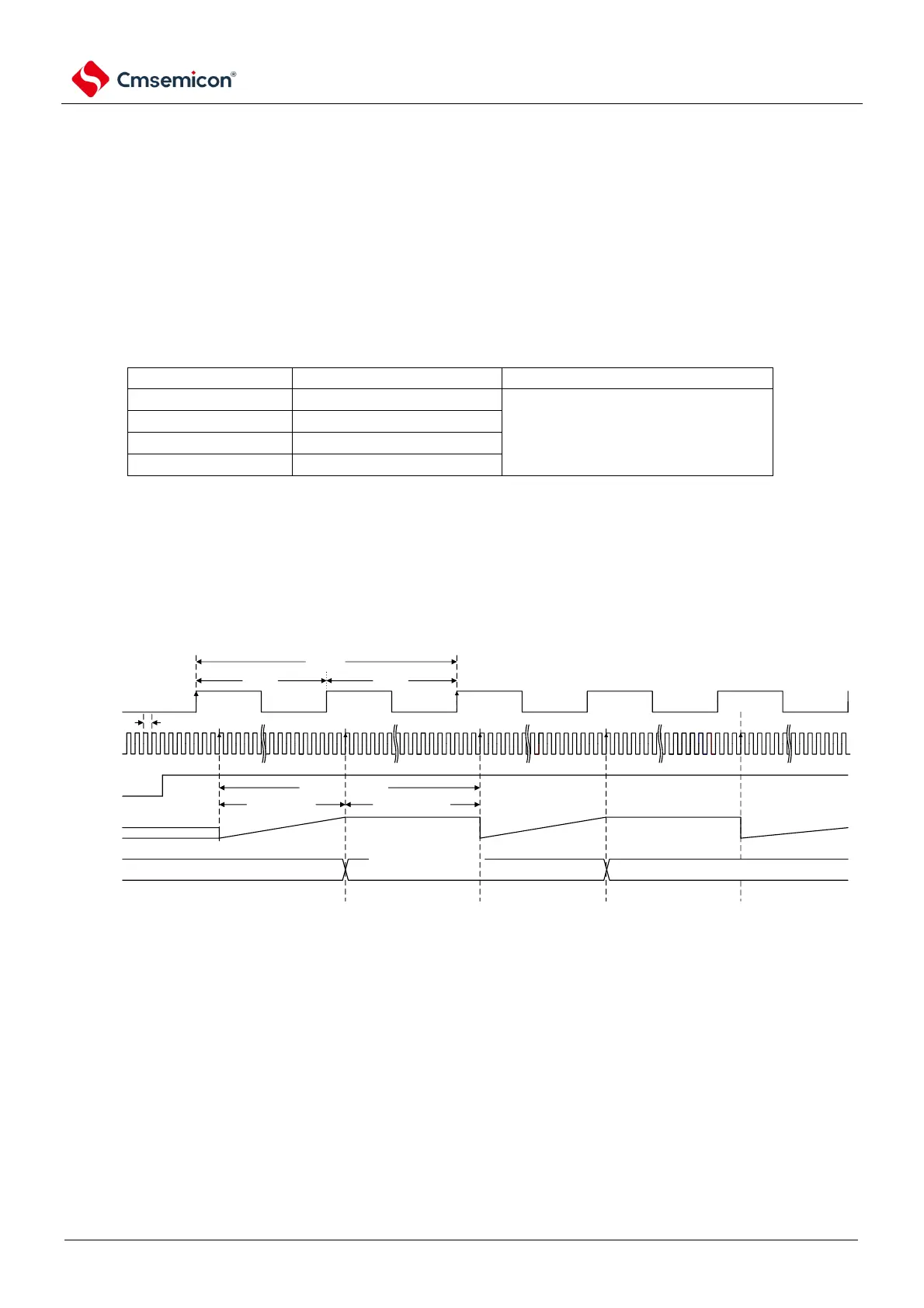
Table 4-11 shows the input frequency and correction period of high-speed internal vibration, and Figure 4-
20 shows the sequence diagram of high-speed internal vibration frequency correction action (detailed).
Table 4-11 High Speed Internal Vibration Input Frequency and Correction Period
Note: FRQSEL4-FRQSEL3 is option byte0 0C2H bit4-bit3
During the frequency measurement phase of the correction cycle, the frequency of the high-speed
internal oscillation is corrected according to the size of the count value and the expected value, using the
high-speed internal vibration count.
Figure 4-20 High-speed internal vibration frequency correction Operation timing diagram
(detailed)
Note: The basic actions of the continuous Operation mode and the interval Operation mode are the
same. The difference is whether the removal of FCST bits is controlled by software or
hardware. In addition, only the system reset can clearly correct the value.