CMS32L051 User Manual |Chapter 5 Universal Timer Unit (Timer4)
www.mcu.com.cn 144 / 703
5.5 Operation of the counter
5.5.1 Count clock (f
TCLK
)
The Count Clock of the General-Purpose Timer Unit (f
TCLK
) can select any of the following clocks via
the CCSmn bit of the timer mode register mn (TMRmn).
•
The CKSmn0 bit and CKSmn1 bit specify the running clock (f
MCK
).
•
The effective edge of the TImn pin input signal.
The general-purpose timer unit is designed to run synchronously with the f
CLK
, so the timing of the count
clock (f
TCLK
) is as follows.
(1) Select the case where CKSmn0 bit and CKSmn1 bit specify the operating clock (f
MCK
) (CCSmn=0).
According to the timer clock selection register m (TPSm) setting, the count clock (f
TCLK
) is f
CLK
~f
CLK
/2
15. However, when selecting a crossover of f
CLK
, the TPSm register selects a clock for a signal that is
high with only 1 f
CLK
cycle from the rising edge. When f
CLK
is selected, it is fixed to high.
To synchronize with f
CLK
, the timer count register mn (TCRmn) counts after delaying 1 f
CLK
clock from
the rising edge of the count clock. For convenience, it is called counting on the rising edge of the counting
clock.
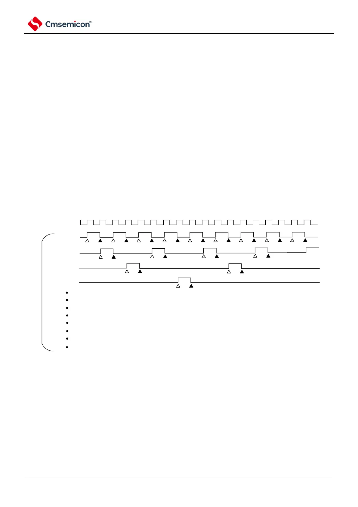
Figure 5-24 Timing of f
CLK
and count clock (f
TCLK
) (in the case of CCSmn=0)
Remark 1. △: Counts the rising edge of the clock
2.f
CLK
: The clock for CPU/peripheral hardware