CMS32L051 User Manual |Chapter 5 Universal Timer Unit (Timer4)
www.mcu.com.cn 139 / 703
5.3.14 Noise filter enable register 2 (NFEN2)
The NFEN2 register sets whether the noise filter is used for the input signal of the timer input pins
of each channel of Element 1. For pins that need to be noise canceled, the corresponding position 1
must be placed for the noise filter to be effective. When the noise filter is active, detect whether the two
clocks are consistent after synchronization through the running clock (fMCK) of the object channel;
When the noise filter is invalid, the synchronization is only made through the running clock (fMCK) of
the object channel.
The NFEN 2 registers are set via 8-bit memory operation instructions. After the reset signal is
generated, the value of the NFEN2 register changes to 00H.
For details, please refer to 5.5.1(2) Selecting the Valid Edge of the TImn Pin Input Signal (CCSmn=1) and 5 .5.2
Start Timing of Counters and Control of 5.7 Timer Inputs (TImn).
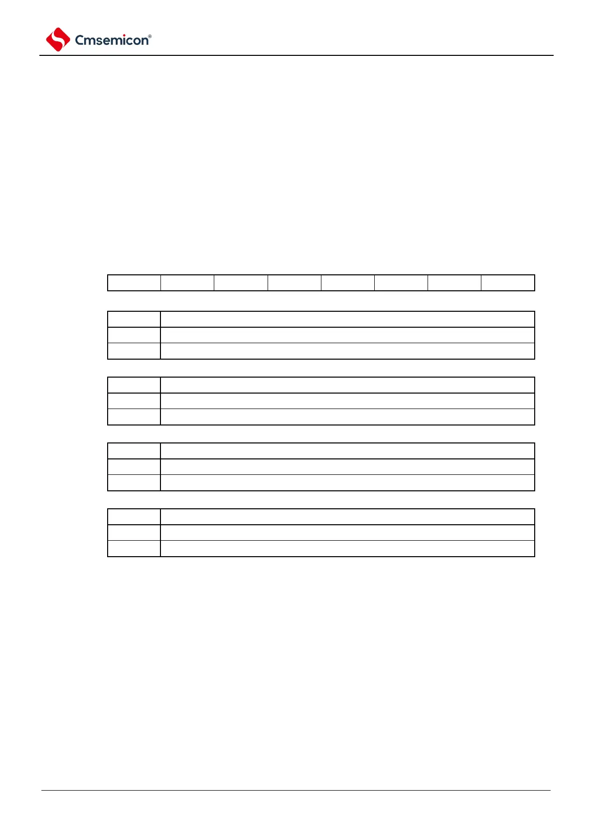
Figure 5-23 Table of noise filter enable register 2 (NFEN2)
Address: 0x40040472
Symbol
7 6 5 4 3 2 1 0
NFEN2