5.8.3 Operates as frequency divider
The clock input to the TI00 pin can be divided and used as a divider for the output of the TO00 pin.
The divider clock frequency of the TO00 output can be calculated using the following equation:
In interval timer mode, the timer count register 00 (TCR00) is used as a decrement counter.
After setting the channel start trigger bit (TS00) of timer channel start register 0 (TS0) to 1, the
value of timer data register 00 (TDR00) is loaded into the TCR00 register by detecting the valid edge of
TI00. In this case, if the MD000 bit of Timer Mode Register 00 (TMR00) is 0, INTTM00 is not output and
TO00 is not alternately output; if the MD000 bit of TMR00 register is 1, INTTM00 is output and TO00 is
alternately output.
The TCR00 register is then decremented by the active edge of the TI00 pin input. If TCR00
becomes 0000H, TO00 alternates the output. At the same time, the value of the TDR00 register is
loaded into the TCR00 register and the count continues.
If you select the detection of the bilateral edge of the TI00 pin input, the duty cycle error of the input clock
affects the divider clock period of the TO00 output.
The clock cycle of the TO00 output contains a sampling error of 1 running clock cycle.
The TDR00 register can be overridden at any time, and the value of the overridden TDR00 register is valid
for the next count period.
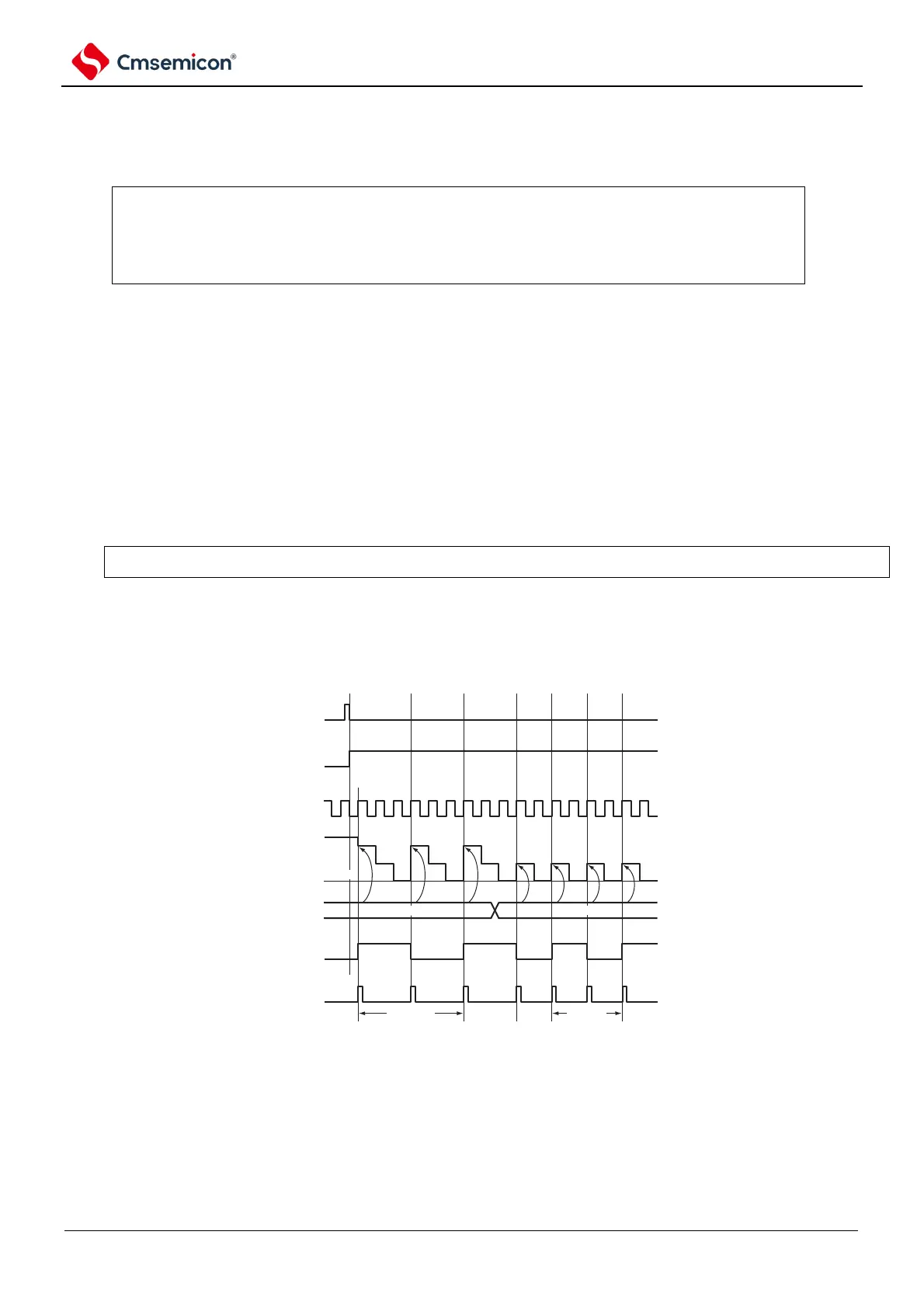
Figure 5-49 Example of basic timing as a frequency divider operation (MD000=1)
TS00
TE00
TI00
TCR00
TDR00
TO00
INTTM00
Note TS00: Bit0 of timer channel start register 0 (TS0)
TE00: Bit0 of timer channel enable for status register 0 (TE0).
TI00: TI00 pin input signal.
TCR00: Timer counter register 00 (TCR00).
TDR00: Timer data register 00 (TDR00).
TO00: TO00 pin output signal.