CMS32L051 User Manual |Chapter 13 Serial Interface SPI
www.mcu.com.cn 462 / 703
13.3.2 SPI operating mode register (SPIM)
SPIM is used to select the operating mode and control the allow or disallow of the operation.
SPIM can be set by 8-bit storage operation instructions.
A reset signal is generated to clear the register to 00H.
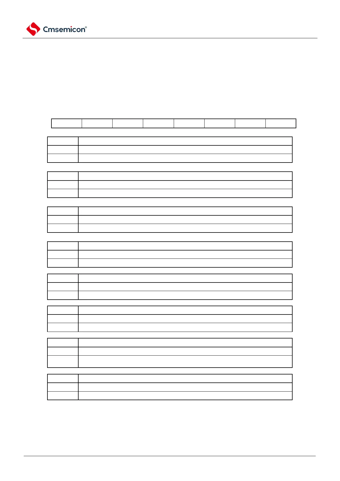
Figure 13-2 Format of mode control register (SPIM)
Address: 0x40042400 After reset: 00HR/W Note 1
Transmit/receive mode control
Data transfer order selection
Performs MSB-first input/output.
Perform LSB- first input/output.
Interrupt source selection
The end of the transfer is interrupted
Null interrupt for sending buffers
The setting of the data length
Receive buffer non-null flag bits
There is no new received valid data in the receive cache
There is valid data received in the receive cache. When the register SDRI is read, the bit is
cleared to 0
Communication status flag bits
Communication is in progress
Note: 1. Bits 0 and 1 are read-only bits.
2. When SPTF=1 (during serial communication), rewriting TRMD, DIR, NSSE is prohibited.
3. The MO or SO output is fixed low when the TRMD is 0.
4. Fix the NSS pin input level to 0 or 1 before setting the bit to 1.