CMS32L051 User Manual |Chapter 11 A/D Converter
www.mcu.com.cn 267 / 703
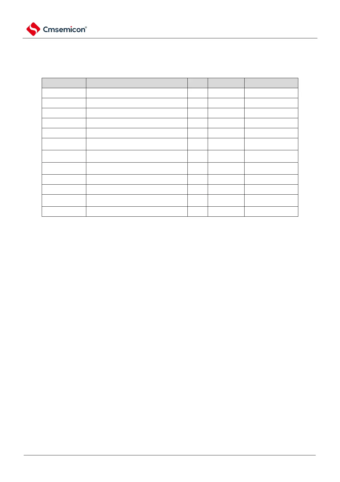
11.2 Control registers of A/D converter
The registers that control the A/D converter are as follows:
Register base address: CSC_BASE=4002_0420H; ADC_BASE=4004_5000H;
PORT_BASE=4004_0000H
Peripheral enable register 0
A/D converter mode register 0
A/D converter mode register 1
A/D converter mode register 2
A/D converter trigger mode register
Analog input channel specification
register
Conversion result comparison lower limit
setting register
Conversion result comparison upper limit
setting register
12-bit A/D conversion result register
8-bit A/D conversion result register
A/D converter sampling time extension
control register
Port mode control register
R: read only, W: write only, R/W: both read and write.
Note 1: When selecting a channel through the ADS registers, the PMC register of the channel pin needs
to be configured as an analog channel.