CMS32L051 User Manual |Chapter 14 Serial interface IICA
www.mcu.com.cn 491 / 703
14.3.3 IICA status register n (IICSn)
This is the register that represents the I
2
C state.
The 8-bit memory operation instruction can read the IICSn register only during the STTn bit being 1 and
waiting. After the reset signal is generated, the value of this register becomes 00H.
Notice In deep sleep mode, the IICSn register is forbidden to read in the Allow Address Matching Wake-Up Function
(WUPn=1) state. In the state where the WUPn bit is 1, it is not related to the INTIICAn interrupt request if the
WUPn bit is changed from 1 to 0 (Stop Wake-On Operate), the change in state is not reflected until the next start
condition or stop condition is detected. Therefore, when using the wake-up function, interrupts arising from the
detection of a stop condition must be allowed (SPIEn=1) and the IICSn register must be read after the interrupt is
detected.
: bit1 of IICA control register n0 (IICCTLn0).
: Bit7 of IICA control register n1 (IICCTLn1).
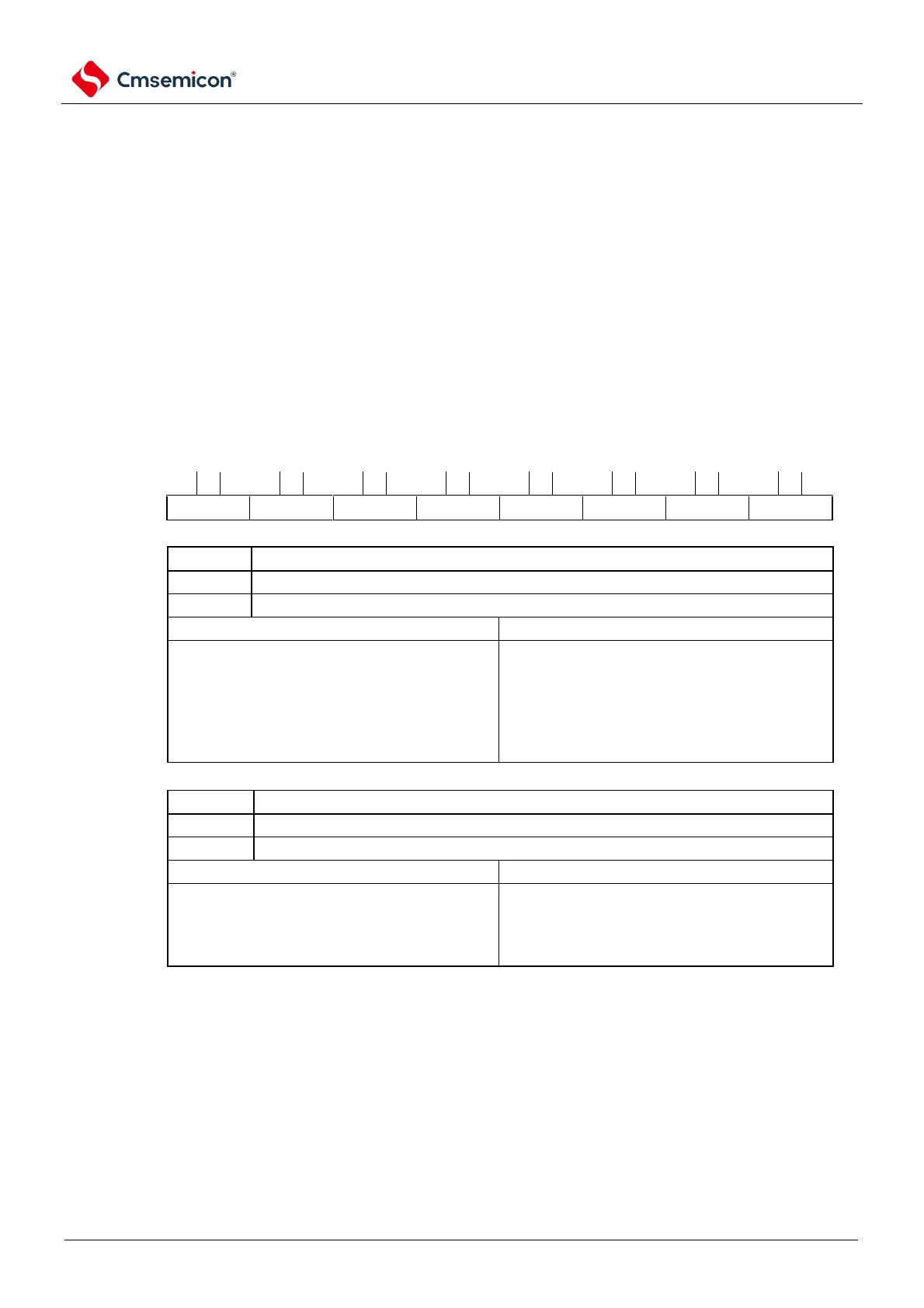
Figure 14-7 Format of IICA status register n (IICSn) (1/3)
Address: 0x40041B51 After reset: 00H R
Confirmation flag for the master status
Slave state or communication standby
Master communication status
Clear condition (MSTSn=0).
stop condition is detected
the ALDn bit is 1 (arbitration failed).
LRELn bit being 1 (exit
communication).
IICEn bit changes from 1 to 0 (stop
running).
Detection of arbitration failures
Indicates that no arbitration occurred or that arbitration was won.
Indicates that arbitration failed. Clear the MSTSn bit.
Clear condition (ALDn=0).
the IICSn register after reading
Note
.
IICEn bit changes from 1 to 0 (stop
running).
Note This bit is cleared even if a bit memory operation instruction is performed on a bit other than the IICSn register.
Therefore, when using the ALDn bit, the data of the ALDn bit must be read before reading the other bits.
Remark 1. LRELn: Bit6 of the IICA control register n0 (IICCTLn0).
IICEn: Bit7 of the IICA control register n0 (IICCTLn0).
2.n=0