5.8.4 Operates as input pulse interval measurement
Counts can be captured at TImn effective edges and the interval between TImn input pulses can be
measured. During the TEmn bit of 1, the software operation (TSmn=1) can also be set to capture the
trigger to capture the count value.
The pulse interval can be calculated using the following calculation formula:
Note: Because the TImn pin input is sampled by the operating clock selected by the CKSmn bit of the timer mode register
mn (TMRmn), an error of 1 run clock is generated.
In capture mode, the timer count register mn (TCRmn) is used as an increment counter.
If the channel start triggers bit (TSmn) of the timer channel start register m (TSm) is set to 1, the
TCRmn register is clocked from 0000H by counting the clock Start incrementing the count.
If a valid edge of the TImn pin input is detected, the count value of the TCRmn register is transferred
(captured) to the timer data register mn (TDRmn) and the TCRmn register is cleared 0000H, and then
output INTTMmn. At this point, if the counter overflows, the OVF position of the timer status register mn
(TSRmn) is 1. If the counter does not overflow, the OVF bit is cleared. After that, continue with the same
run.
While snapping the count value to the TDRmn register, the OVF bit of the TSRmn register is updated
depending on whether an overflow occurred during the measurement and the overflow state of the
captured value can be confirmed.
Even if the counter performs a full count of 2 cycles or more, it is considered that an overflow occurs
and the OVF position of the TSRmn register is 1. However, in the event of 2 or more overflows, the
interval value cannot be measured normally by the OVF bit.
Set the STSmn2 to STSmn0 bits of the TMRmn register to 001B and use the valid edges of TImn for start
trigger and capture trigger.
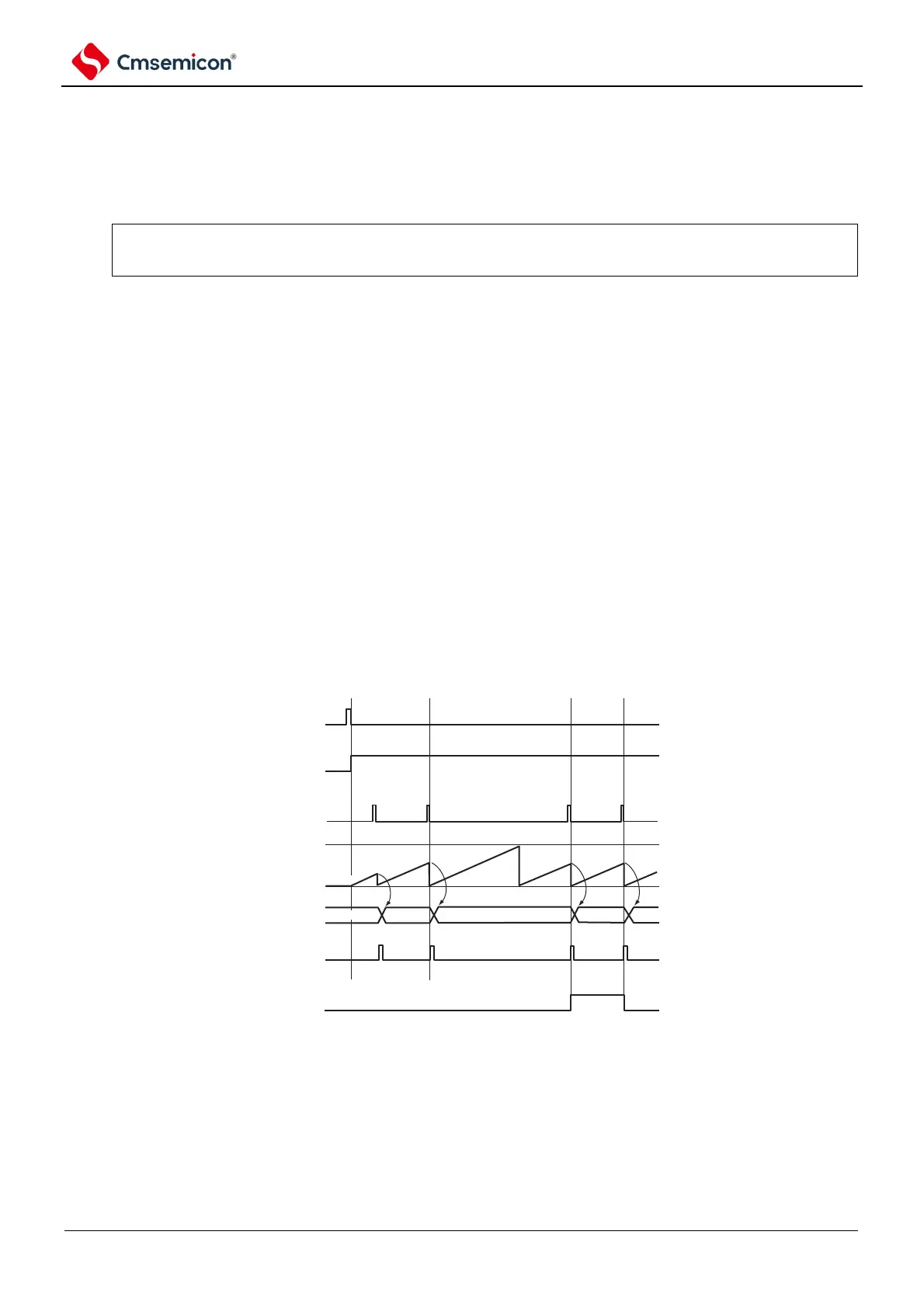
Figure 5-52 Example of basic timing of operation as input pulse interval measurement (MDmn0=0).
TSmn
TEmn
TImn
TCRmn
TDRmn
INTTMmn
OVF
Note 1. m: unit number (m= 0) n: channel number (n=0 ~ 3).
2. TSmn: Bit n of timer channel start register m (TSm)
TEmn: Bit n of timer channel enable status registerm (TEm).
TImn: TImn pin input signal.
TCRmn: Timer counter register mn (TCRmn).
TDRmn: Timer data register mn (TDRmn).
OVF: Bit 0 of the timer status register mn (TSRmn).