EasyManua.ls Logo

Cmsemicon CMS32L051 - DMA Control Data Areas and DMA Vector Table Areas Allocation

Default Icon
703 pages
Print Icon
To Next Page IconTo Next Page
To Previous Page IconTo Previous Page
Loading...
V1.2.2
CMS32L051 User Manual |Chapter 16 Enhanced DMA
www.mcu.com.cn 578 / 703
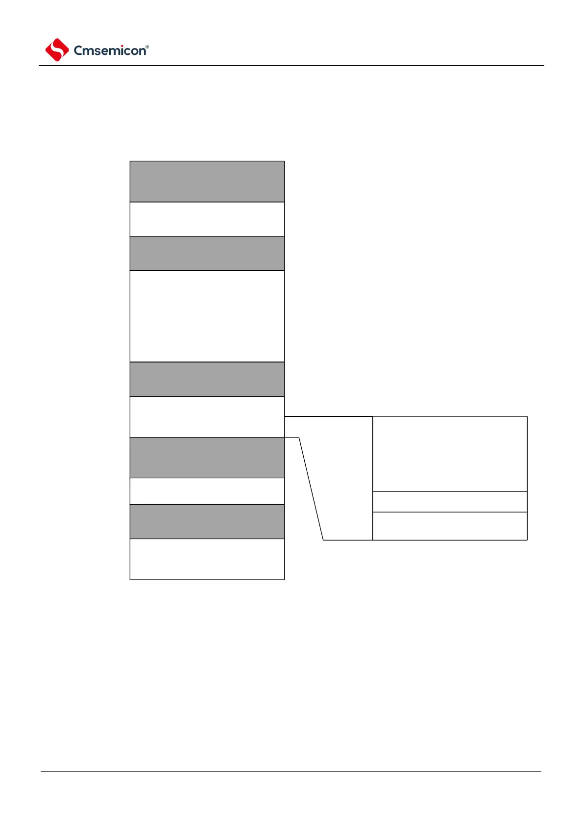
16.3.1 DMA control data areas and DMA vector table areas allocation
The control data allocated to the DMA and the 416-byte region of the vector table are set to the RAM
area via the DMABAR register.
An example of a memory image with a DMABAR register set to 20000000H is shown in Figure 16-2.
The 384 bytes of DMA control data area in the DMA unused space can be used as RAM.
Figure 16-2 Example of memory image when the DMABAR register is set to 20000000H
reserved
Cortex-M0+
dedicated peripherial
resource region
reserved
peripherial resource region
reserved
SRAM
4KB
reserved
data flash
1.5KB
reserved
main flash region
32KB
FFFF_FFFFH
E00F_FFFFH
E000_0000H
4005_FFFFH
4000_0000H
2000_0FFFH
2000_0000H
0050_05FFH
0050_0000H
0000_7FFFH
0000_0000H
DTC control
data region
384 bytes
Reserved region
8 bytes
DTC vector table region
24 bytes
20000000H
20000018H
20000020H
2000019FH
200001A0H
DMA usage region
416 bytes

Table of Contents

Related product manuals