CMS32L051 User Manual |Chapter 14 Serial interface IICA
www.mcu.com.cn 486 / 703
14.3.1 Peripheral enable register 0 (PER0)
The PER0 register is a register that sets the clock to be allowed or disallowed to be supplied to each
peripheral hardware. Reduce power consumption and noise by stopping clocking unused hardware.
To use the serial interface IICAn, bit4 (IICAEN) must be set to 1.
The PER0 register is set via an 8-bit memory operation command.
After the reset signal is generated, the value of this register becomes 00H.
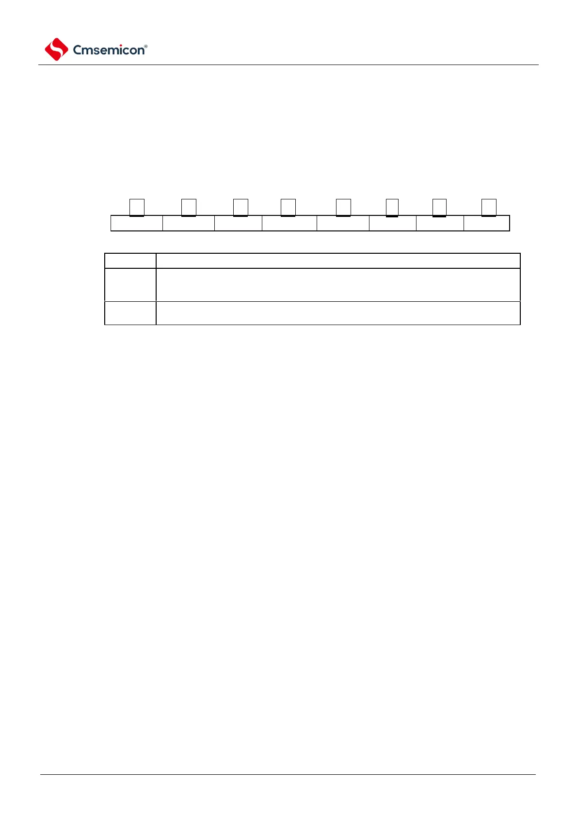
Figure 14-5 the peripheral Enable register 0 (PER0)
Address: 40020 420H After reset: 00HR/W
symbol
PER0
Stop supplying the input clock.
IICA using SFR.
IICA is in a reset state.
Note 1 To set the serial interface IICA, the following registers must first be set in the state where the IICAEN bit is 1.
When the IICAEN bit is 0, the value of the control register of the serial interface IICA is the initial value, ignoring
the write operation (port multiplexing function configuration register (PxxCFG), port mode register (PM xx) and port
mode control registers (PMCxx).
IICA control register n0 (IICCTLn0).
IICA flag register n (IICFn).
IICA status register n (IICSn).
IICA control register n1 (IICCTLn1).
IICA low level width setting register n (IICWLn).
IICA high level width setting register n (IICWHn).
Remark n=0
14.3.2 IICA control register n0 (IICCTLn0)
This is a register that allows or stops I
2
C operation, sets the wait sequence, and sets other I
2
C operations.
The IICCTLn0 register is set via an 8-bit memory operation command. However, the SPIEn, WTIMn, and
ACKEn bits must be set when the IICEn bit is 0 or during the wait, and the IICEn must be set. Bits can be set
simultaneously when they are set from 0 to 1.
After the reset signal is generated, the value of this register becomes 00H.
Remark n=0