CMS32L051 User Manual |Chapter 14 Serial interface IICA
www.mcu.com.cn 487 / 703
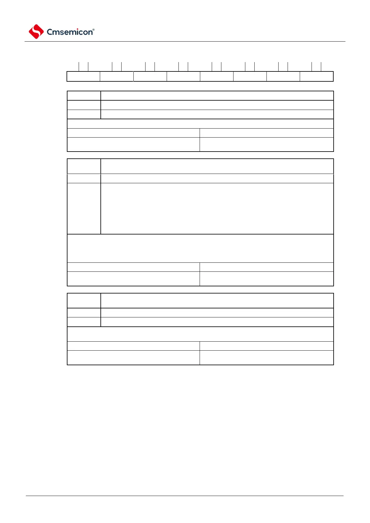
Figure 14-6 Format of IICA control register n0 (IICCTLn0) (1/4)
Address: 0x40041A30 After reset: 00HR/W
Disable operation. Reset
Note
1
to IICA status register n (IICSn) and stop internal operation.
This bit must be 1 in the state where the SCLAn line and the SDAAn line are high.
Clear condition (IICEn=0).
Exit the current communication and enter standby. Automatically clear 0 after execution.
It is used in cases where an extension code that is not related to the local station is received,
etc.
The SCLAn line and the SDAAn line become high-impedance.
The following flags in IICA control register n0 (IICCTLn0) and IICA status register n (IICSn)
are cleared 0:
Becomes standby to exit communication until the following communication participation conditions are
met.
Clear condition (LRELn=0).
Release the wait. Automatically clears after the wait is released.
If the WRELn bit (unwait) is set during the 9th clock wait in the transmit state (TRCn=1), the SDAAn line
becomes high impedance state (TRCn=0).
Clear condition (WRELn=0).
Note 1. For IICA shift register n (IICAn), IICA flag register n (IICFn). STCFn bits and IICBSYn bits and CLDn of IICA
control register n1 (IICCTLn1). The bits and DADn bits are reset.
2. In the state where the IICEn bit is 0, the signal for this bit is invalid.
3. The read value of LRELn bits and WRELn bits is always 0.
Notice If I
2
C operation is allowed (IICEn=1) when the SCLAn line is high, the SDAAn line is low and the digital filter is ON
(DFCn=1 of the IICCTLn1 register), the start condition is detected immediately. In this case, the LRELn bit must
be set to "1" by the bit memory operation instruction continuously after I
2
C operation is allowed (IICEn=1).
Remark n=0