CMS32L051 User Manual |Chapter 15 IrDA
www.mcu.com.cn 568 / 703
Chapter 15 IrDA
IrDA enables the transmission and reception of IrDA communication waveforms in accordance with the
IrDA (InfraredDataAssociation) 1.0 protocol in cooperation with the Universal Serial Communication Unit
(SCI).
15.1 Function of IrDA
If the IrDA function is set to active through the IRE bit of the IRCR register, SCI's TxD2 signal and RxD2
signal can encode or decode the waveform that conforms to the IrDA1.0 protocol (IrTxD/IrRxD pins), and then
implement infrared transmission and reception that supports the IrDA1.0 protocol by connecting the
transmitter or receiver that transmits/receives infrared rays.
In systems that support the IrDA1.0 protocol, after communication begins at a transfer rate of 9600bps,
the transfer rate can be changed as needed. IrDA does not have a built-in function to automatically change the
transfer rate, so the settings must be changed by software to change the transfer rate.
When selecting a high-speed internal oscillator (f
IH
=24, 12, 6, 3MHz), the following baud rates can be set.
115.2kbps, 57.6kbps, 38.4kbps, 19.2kbps, 9600bps, 2400bps
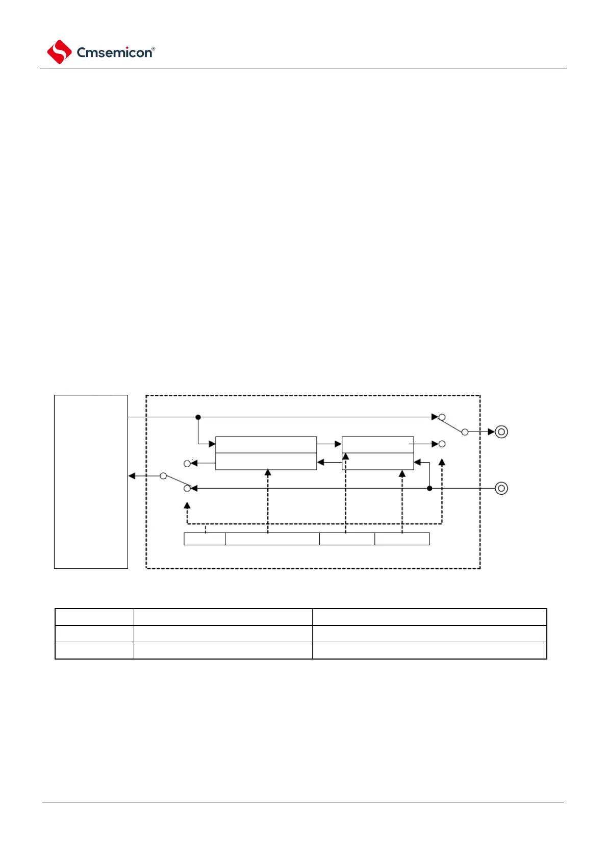
A schematic block diagram of the collaboration between IrDA and SCI is shown in Figure 15-1.
Figure 15-1 Block diagram of the cooperation between IrDA and SCI