CMS32L051 User Manual |Chapter 14 Serial interface IICA
www.mcu.com.cn 500 / 703
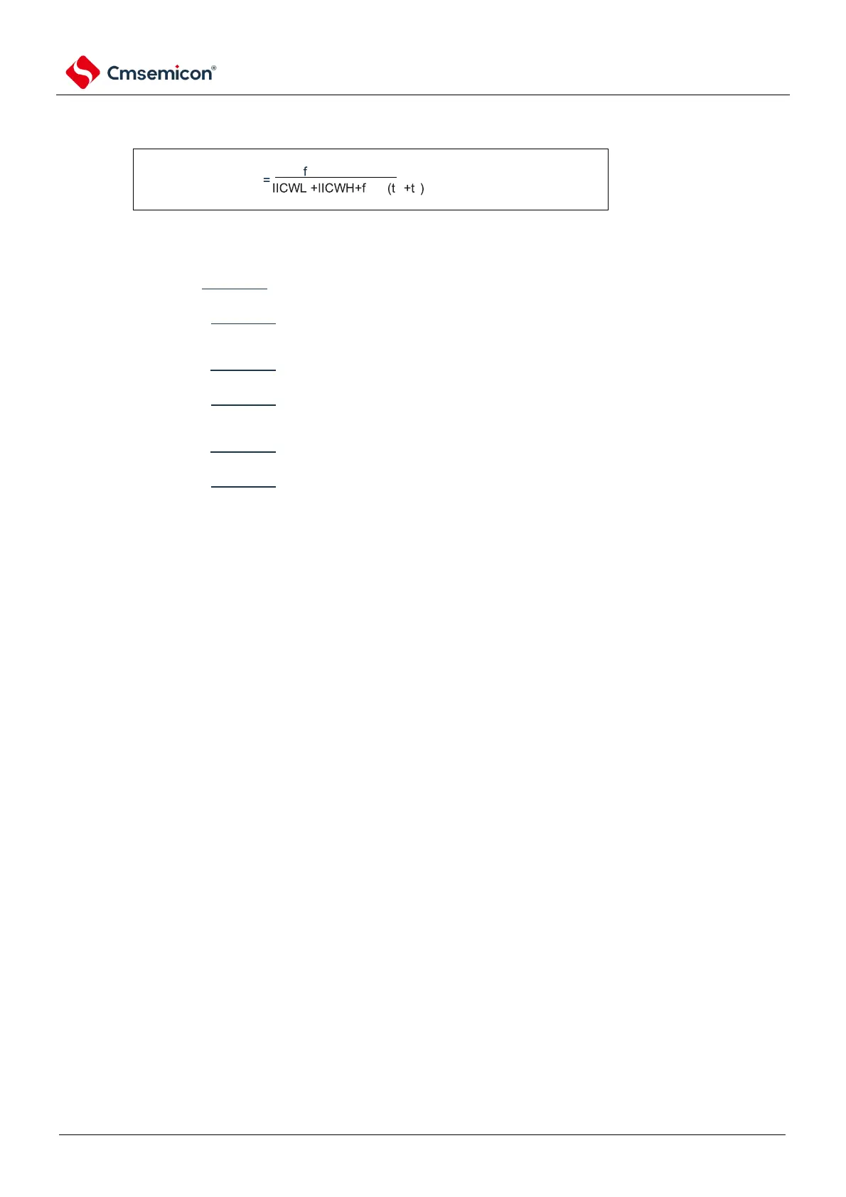
14.4.2 Setting the transmit clock via IICWLn register and IICWHn register
(1) The setting method of the master controller transmitting the clock
At this point, the best config values for the IICWLn register and the IICWHn register are as follows:
(All fractional parts of the config valueare rounded)
Quick mode
IICWLn=
IICWHn=(
Standard mode
IICWLn=
IICWHn=(
Enhanced quick mode
IICWLn=
IICWHn=(
(2) Setting method for secondary IICWLn registers and IICWHn registers
(All fractional parts of the config valueare rounded)
Quick mode
IICWLn=1.3us x f
MCK
IICWHn=(1.2ust
R
t
F
) x f
MCK
Standard mode
IICWLn=4.7us x f
MCK
IICWHn=(5.3ust
R
t
F
) x f
MCK
Enhanced quick mode
IICWLn=0.50us x f
MCK
IICWHn=(0.50ust
R
t
F
) x f
MCK
Note 1. The maximum operating frequency of the IICA operating clock (f
MCK
) is 20MHz (Max.). IICA control register n1
(IICCTLn1) must only be used when the f
CLK
exceeds 20MHz bit0 (PRSn) is set to 1.
2. In the case of setting the transmission clock, it is necessary to pay attention to the minimum operating frequency
of f
CLK
. The minimum operating frequency of the f
CLK
for the serial interface IICA depends on the operating
mode.
Fast mode: f
CLK
= 3.5MHz (Min.)
Enhanced Fast Mode: f
CLK
= 10MHz (Min.)
Standard mode: f
CLK
= 1MHz (Min.)
Remark 1. Because the rise time (t
R
) and fall time (t
F
) of the SDAAn signal and the SCLAn signal vary depending on the pull-
up resistance and the wiring capacitance, they must be calculated separately.
2. IICWLn: IICA low level width n setting register
IICWHn: IICA high level width setting register n
t
F
: Drop time for SDAAn signal and SCLAn signal
t
R
: Rise time of SDAAn signal and SCLAn signal
f
MCK
: IICA operation at the clock frequency
3. n=0