CMS32L051 User Manual |Chapter 21 Reset Function
www.mcu.com.cn 641 / 703
21.1 Register for confirming the reset source
21.1.1 Reset control flag register (RESF)
The CMS32L051 microcontroller has multiple internal reset sources. The Reset Control Flag
Register (RESF) holds the reset source where the reset request occurred. RESF registers can be read
via 8-bit memory operation instructions.
SYSRF, WDTRF, RPERF, are cleared by the input of RESETB, the reset of the power-on reset (POR)
circuit, and the reading of the RESF register IAWRF, LVIRF logo. To determine the reset source, the value
of the RESF register must be saved to any RAM and then judged by its RAM value.
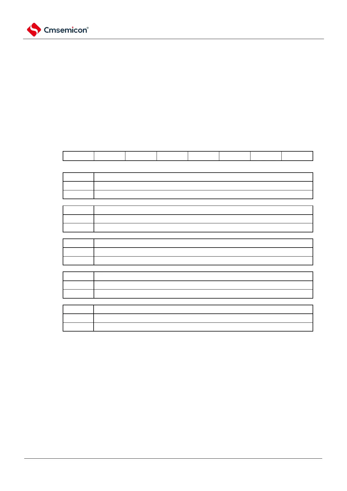
Figure 21-4 Format of reset control flag register (RESF)
Address: 40020440H After reset: Indefinite value
Note
1 R
Symbol
7 6 5 4 3 2 1 0
FRSR
An internal reset request resulting from a system reset request bit being set
No internal reset requests were made or the RESF registers were cleared.
An internal reset request is generated.
The watchdog timer (WDT) generates an internal reset request
No internal reset requests were made or the RESF registers were cleared.
An internal reset request is generated.
An internal reset request is generated by a RAM parity error
No internal reset requests were made or the RESF registers were cleared.
An internal reset request is generated.
Internal reset requests generated by access illegal memory
No internal reset requests were made or the RESF registers were cleared.
An internal reset request is generated.
An internal reset request generated by a voltage sense circuit (LVD)
No internal reset requests were made or the RESF registers were cleared.
An internal reset request is generated.
Note 1 Varies depending on the reset source. Please refer to Table 21-2.
Note In the case of allowing RAM parity error reset (RPERDIS=0), the RAM area must be initialized when accessing
data. When executing instructions from the RAM area, the area of used RAM area + 10 bytes must be initialized. By
generating a reset, it enters a state that allows RAM parity error reset (RPERDIS=0). For more information, see 26.3.3
RAM Parity Error Detection Function