EasyManua.ls Logo

Cmsemicon CMS32L051 - Chapter 6 Function of EPWM Output Control Circuit; 6.1 Structure of the output control circuit

Default Icon
703 pages
Print Icon
To Next Page IconTo Next Page
To Previous Page IconTo Previous Page
Loading...
V1.2.2
CMS32L051 User Manual |Chapter 6 Function of EPWM Output Control Circuit
www.mcu.com.cn 205 / 703
Chapter 6 Function of EPWM Output Control Circuit
Using the PWM output function of Timer, one DC motor or two stepper motors can be controlled. The
output can be truncated by truncating the source CMP0 output, the INTP0 input, and the EVENTC event. The
software allows you to select from four outputs: Hi-Z output, low output, high output, and anti-truncation output
during forced truncation.
6.1 Structure of the output control circuit
The EPWM output control circuit consists of the following hardware.
Table 6-1 Structure of the output control circuit of EPWM
Item
Structure
Control registers
EPWM input source selection register (EPWMSRC).
EPWM output control register (EPWMCTL).
EPWM force truncated input selection register (EPWMSTC).
EPWM force truncated output selection register (EPWMSTL).
EPWM Status Register (EPWMSTR).
output
EPWM output (EPWMO00~EPWMOP07)
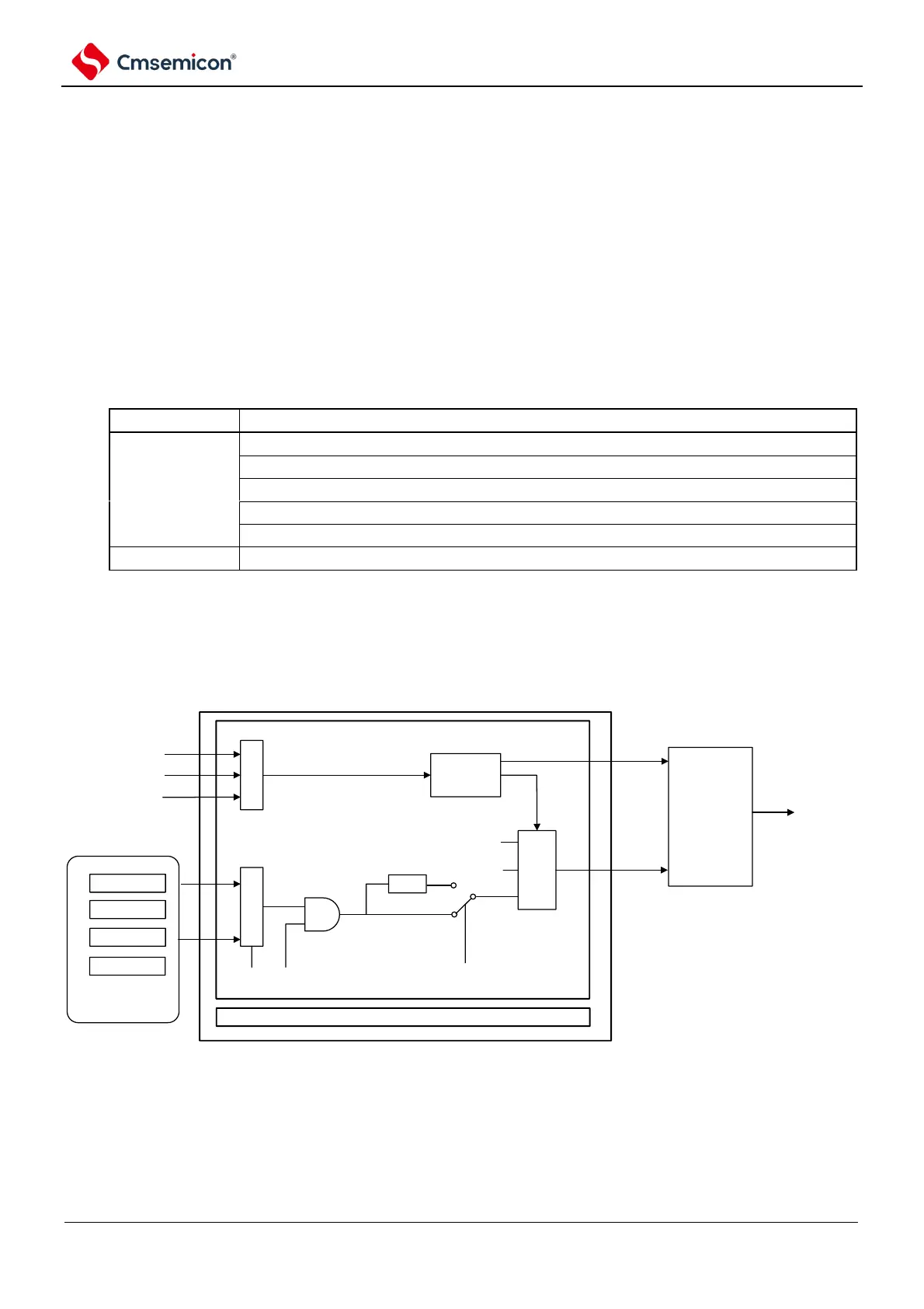
The block diagram of the EPWM output control circuit is shown in Figure 6-1.
Figure 6-1 Block diagram of EPWM output control circuit
selector
Intp0 input
Comparator output
EVENTC event
CH3
CH2
CH1
CH0
Timer array unit PWM
output (CH1, CH3)
selector
control
circuit
SRC00 OE00
Negate
IE00
Output
data
selecti
on
High
Low
EPWMO00
Channel 0
Channel 1~Channel 7 (the same structure as channel 0)
PORT control
HIZ control
output data

Table of Contents

Related product manuals