CMS32L051 User Manual |Chapter 5 Universal Timer Unit (Timer4)
www.mcu.com.cn 204 / 703
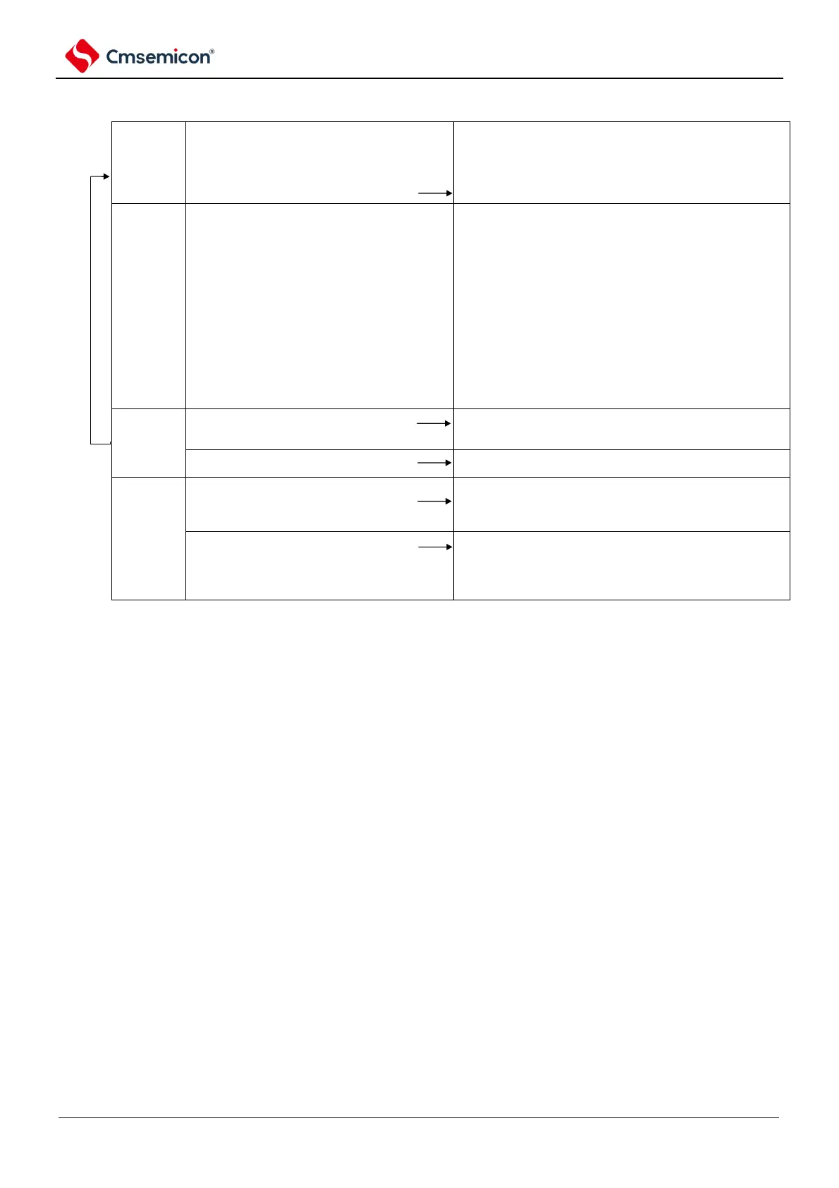
Figure 5-78 Operation procedure for multiple PWM output function (in case of 2 PWM outputs) (2/2)
(only during restart operation, TOEmp bit and TOEmq bit
(slave) will set to '1').
Set TSmn bit(master), TSmp bit and TSmq bit (slave) of timer
channel start register m(TSm) all set to '1' at the same time.
Because TSmn bit, TSmp and TSmq bit are all trigger bits,
thus automatically return to '0'.
TEmn bit and TEmp bit both turns into '1'.
Master channel start counting and generate INTTMmn. Using this trigger,
slave channel also start counting.
forbidden modifying TMRmn register and TMRmp register and
TOMmn bit, TOMmp bit, TOLmn bit and TOLmp bit
configuration.
can mmodify TDRMn register and TDRmp register
configuration after master channel generates INTTMmn.
Can read TCRmn reigsrer and TCRmp register anytime.
can not use TSRmn register and TSRmp register.
master channel load TDRmn register value into Timer counting register
(TCRmn) and perform decremental counting. If TCRmn counts till "0000H",
then generating INTTMmn. At the same time, load TDRmn register value into
TCRmn register and restart decremental counting.
Slave channel 1 use INTTMmn of master channel as trigger, will load TDRmp
register value into TCRmp regiter and counter start decremental counting. 1
counting clock cycle after master chanel outputs INTTMmn, it sets T0mp
otuput voltage to valid voltage level. Then, if TCRmp count reaches "0000H",
then set T0mp output voltage set to invalid votlage levle then stoop counting.
Slave channel 2 use INTTMmn of master channel as trigger, will load TDRmq
register value into TCRmq regiter and counter start decremental counting. 1
counting clock cycle after master chanel outputs INTTMmn, it sets T0mq
otuput voltage to valid voltage level. Then, if TCRmq count reaches "0000H",
then set T0mq output voltage set to invalid votlage levle then stoop counting.
Thereafter, the process repeats.
set TTmn bit (master), TTmp bit and TTmq bit(slave) to '1'.
Because TTmn bit, TTmp bit, TTmq bit are trigger bits, thus
automatically return to '0'.
TEmn bit, Temp bit and Temq turn into '0' and stop counting.
TCRmn, TCRmp TCRmq registers hold counted value and stop counting.
T0mp and T0mq output not initialized and remains unchanged.
set TOEmp bit and TOEmq bit of slave channel to '0', and
configure Tomp and TOmq bit.
T0mp pin and T0mq pin output T0mp and T0mq configured voltage level.
Scenarios to maintain T0mp pin and Tomq pin output voltage:
set T0mp bit and Tomq bit to '0'.
In case T0mp pin and Tomq output voltage does not need to
be held: no configuration requried
maintain T0mp pin and Tomq output voltage via Port function.
set TM4mEN bit of peripheral enable register 0 (PER0) to '1'
Timer Unit m input clock is not been provided.Perform initialization to all
circuit and SFR of all channels.
(T0mp bit and T0mq bit turn into '0' and T0mp pin and Tomq becomes port
function)
(TO00 bit turns into '0' and TO00 pin becomes port function)
Note m: unit number (m= 0,1) n: master channel number (n=0).
p: slave channel number q: slave channel number
n<p<(p and q are integers greater than n)