EasyManua.ls Logo

Cmsemicon CMS32L051 - Port Mode Register (Pmxx)

Default Icon
703 pages
Print Icon
To Next Page IconTo Next Page
To Previous Page IconTo Previous Page
Loading...
V1.2.2
CMS32L051 User Manual |Chapter 2 Pin Function
www.mcu.com.cn 21 / 703
2.3.1 Port mode register (PMxx)
When a port is used as a digital channel, this is the register that sets its input/output in bits. After
the reset signal is generated, the ports except the P130 port default to the input state. When using a
port pin as a pin for the multiplexed function, it must be set with reference to 2.5 Register Settings
When Using the Multiplexing Function.
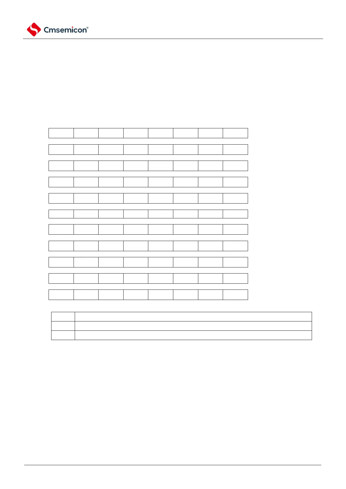
Register address = base address + offset address; the base address of the PM register is
0x40040000, and the offset address is shown in the figure below.
Figure 2-1 Format of port mode register
symbol
7
6
5
4
3
2
1
0
offset
address
after
reset
R/W
PM0
1
1
1
1
1
1
PM01
PM00
0x020
FFH
R/W
PM1
PM17
PM16
PM15
PM14
PM13
PM12
PM11
PM10
0x021
FFH
R/W
PM2
PM27
PM26
PM25
PM24
PM23
PM22
PM21
PM20
0x022
FFH
R/W
PM3
1
1
1
1
1
1
PM31
PM30
0x023
FFH
R/W
PM4
1
1
1
1
1
1
PM41
PM40
0x024
FFH
R/W
PM5
1
1
1
1
1
1
PM51
PM50
0x025
FFH
R/W
PM6
1
1
1
1
PM63
PM62
PM61
PM60
0x026
FFH
R/W
PM7
1
1
PM75
PM74
PM73
PM72
PM71
PM70
0x027
FFH
R/W
PM12
1
1
1
PM124
PM123
PM122
PM121
PM120
0x02C
FFH
R/W
PM13
PM137
PM136
1
1
1
1
1
PM130
0x02D
FEH
R/W
PM14
PM147
PM146
1
1
1
1
1
PM140
0x02E
FFH
R/W
PMmn
Selection of input/output modes for the Pmn pin (m=0~7, 12~14, n=0~7.)
0
Output mode (used as the output port (output buffer ON)).
1
Input mode (used as the input port (output buffer OFF)).
Note 1: The initial value must be set for the unassigned bits.

Table of Contents

Related product manuals