CMS32L051 User Manual |Chapter 16 Enhanced DMA
www.mcu.com.cn 589 / 703
16.3.11 DMA boot enable register i (DMAENi) (i=0~2).
This is the 8-bit register that controls the boot of the DMA through each interrupt source. The
corresponding connection between the interrupt source and the DMAENi0~DMAENi7 bits is shown in
Table 16-6. DMAENi registers can be set via 8-bit memory operation instructions.
Note 1. The DMAENi0~DMAENi7 bits must be changed at the boot source that does not produce the corresponding bits.
2. DMAENi registers cannot be accessed via DMA transfer.
3. The assigned function varies from product to product, and the bits without the assigned function must be set to "0".
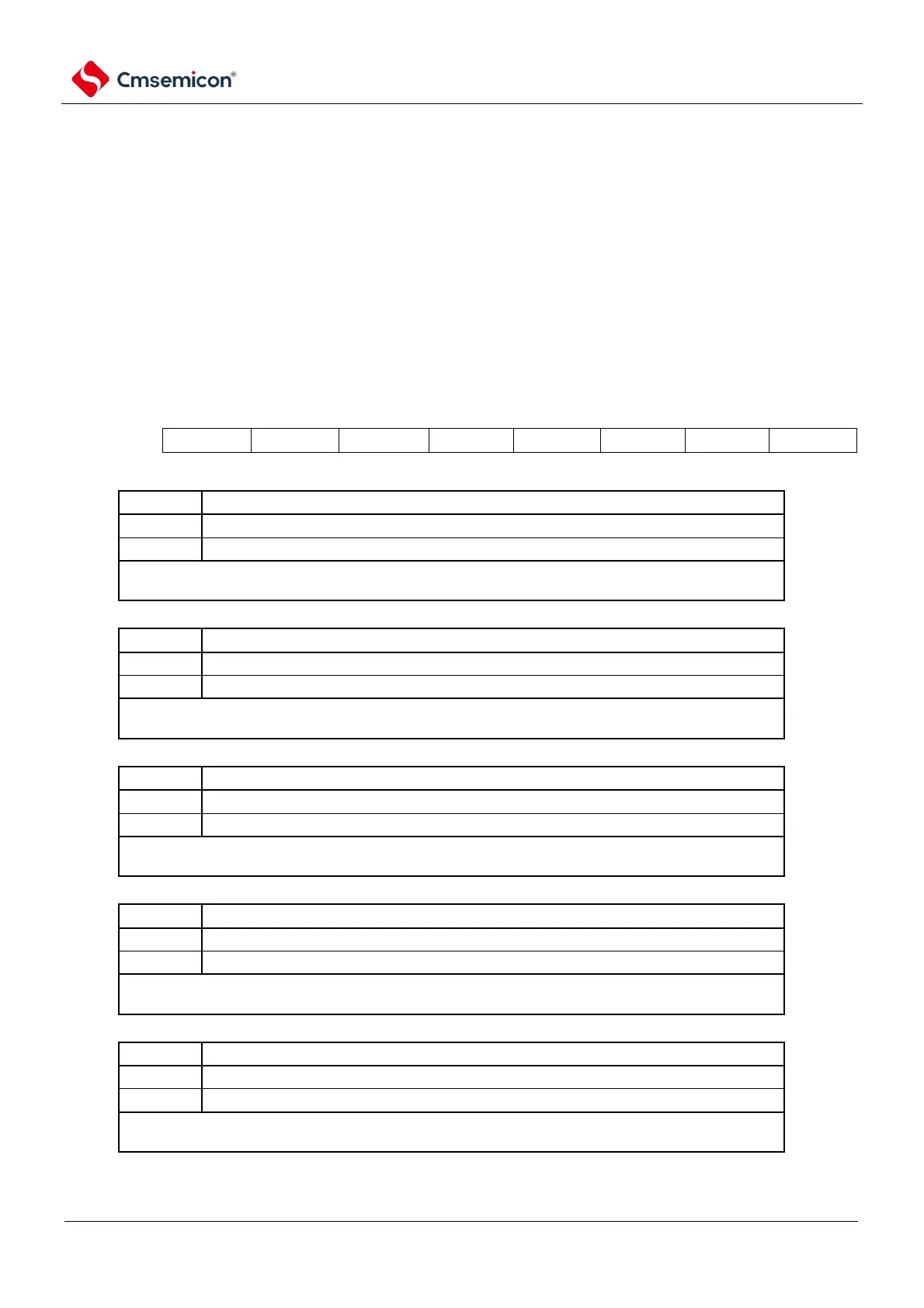
Figure 16-12 Format of the enable register i (DMAENi) (i=0~2)
Address:
40005000H(DMAEN0), 40005001H(DMAEN1),
40005002H(DMAEN2)
After reset:00H
R/W
Depending on the condition under which the end-of-transmission interrupt occurs, the DMAENi7 bit
becomes 0 (disable start).
Depending on the conditions under which the end-of-transmission interrupt occurs, the DMAENi6 bit
becomes 0 (disable start-up).
Depending on the condition under which the end-of-transmission interrupt occurs, the DMAENi5 bit
becomes 0 (disable start).
Depending on the conditions under which the end-of-transmission interrupt occurs, the DMAENi4 bit
becomes 0 (disable start-up).
Depending on the condition under which the end-of-transmission interrupt occurs, the DMAENi3 bit
becomes 0 (disable start-up).