CMS32L051 User Manual |Chapter 6 Function of EPWM Output Control Circuit
www.mcu.com.cn 216 / 703
6.4.3 Example of register setting
In this example, the EPWM source selection registers (EPWMSRC) and EPWM control registers
(EPWMCTL) are initialised to simultaneously output a waveform of positive rotation from EPWM00 to
EPWM05 to the BLDC motor.
1. Set EPWMSRC5 to EPWMSRC0 in the EPWMSRC register to 0 and channel 1 of Timer as
the input source of EPWMO00 ~ EPWMO05.
2. Set EPWMOE3 to EPWMOE0 in the EPWMCTL register to 1 to allow EPWMO03 ~
EPWM00 to be output. Set EPWMIE3 to EPWMIE0 of EPWMCTL register to 0, EPWMO00 ~
EPWMO03 will be output in positive direction.
3. Set EPWMOE5 to EPWMOE4 in the EPWMCTL register to 1 to allow EPWMO05 to
EPWM04 to be output. Set EPWMIE5 ~ EPWMIE4 in the EPWMCTL register to 1 to reverse
the output of EPWMO04~ EPWMO05.
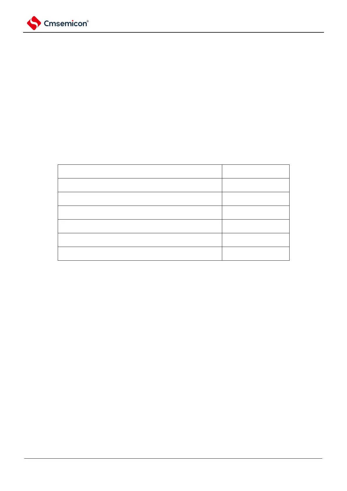
Table 6-4 Example of setting the EPWMCTL0 register
Setting value of the
EPWMCTL
State (1): The rising edge of Hall a disables U+, U+ reverse
outputs, allowing V, Vforward outputs.
State (2): The Hall c falling edge allows U+, U+ forward
output, and disables W, W reverse outputs.
State (3): The Hall b rising edge disables V+, V+ reverse
outputs, allowing W, W forward outputs.
State (4): The falling edge of Hall A allows V+, V+ forward
output, disables U, Ureverse output.
State (5): The Hall c rising edge disables W+, W+ reverse
outputs, allowing U, Uforward outputs.
State (6): The Hallb falling edge allows W+, W+ forward
outputs, and V, Vreverse outputs are disabled.